1. Introduction
This document lists the different functionalities available in the Discover simulator.
First, we will give an introduction to features that apply across all modules.
Secondly, we will detail each module individually, including each of the tasks the user needs to complete in order to progress in the simulation.
2. General operation
2.1. Controllers
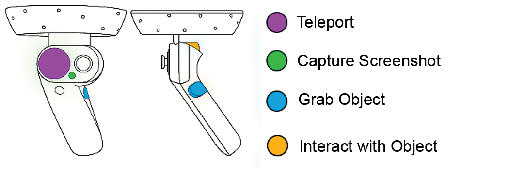
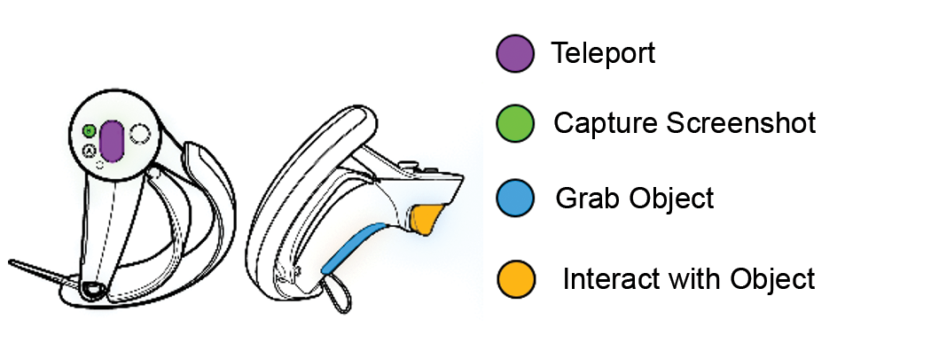
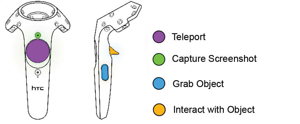
The application is compatible with all OpenXR complient headsets. Depending on the virtual reality headset used, the controllers and hence the associated keys are different.
Windows Mixed Reality
Valve Index
HTC Vive
Oculus Rift

PICO 4

2.2. Authentication
2.2.1. Main menu

When the application is launched, the user is in a main room called the "lobby" where a screen displaying the main menu of the simulator is located in front of him.
The main menu allows the user to authenticate themselves and to select an exercise to perform. At the end of each exercise, the user will be teleported back to the lobby.

The main menu is organised as follows:
-
Class selection (online mode only): classes are configured on the Vulcan online platform
-
Visual progress indicator in the authentication and exercise choice pages:
-
Authentication
-
Choice of module
-
Choice of level
-
Choice of exercise
-
-
Switching to offline mode: the exercises are no longer retrieved from Vulcan and the results will not be sent back to Vulcan. A generic user named Demo is then used instead of a student connected to Vulcan.
-
Displaying the parameters screen: the parameters screen allows, among other things, to change the language of the simulator.
-
Quitting the application
2.2.2. Class selection
Initially, it is necessary to choose the class in which the user who wants to launch an exercise is located.
This menu is only displayed when the simulator is connected to the online platform Vulcan.

2.2.3. User selection
Once the class has been selected, the user must be authenticated. Clicking on the user’s name will bring up a window in which the user’s PIN code, a four-digit number set in Vulcan, must be entered. Users who are not assigned to a Discover learning path will appear in grey. It will not be possible to select them on the simulator.

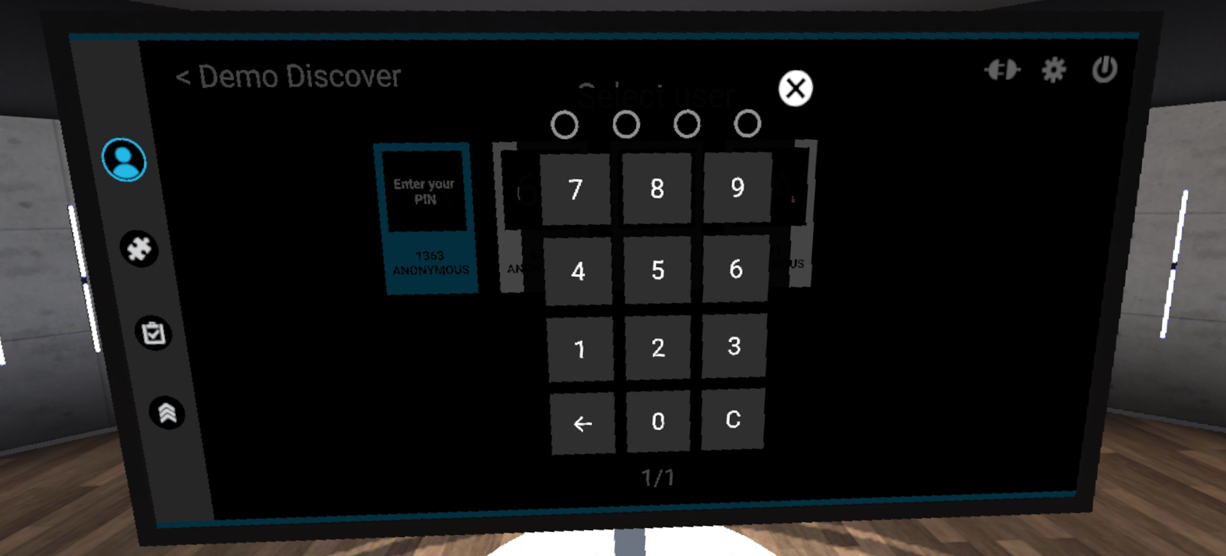
In offline mode, a demo user will be automatically selected.
2.3. Exercise selection
2.3.1. Module selection
Once the user is authenticated, the module selection menu is displayed.
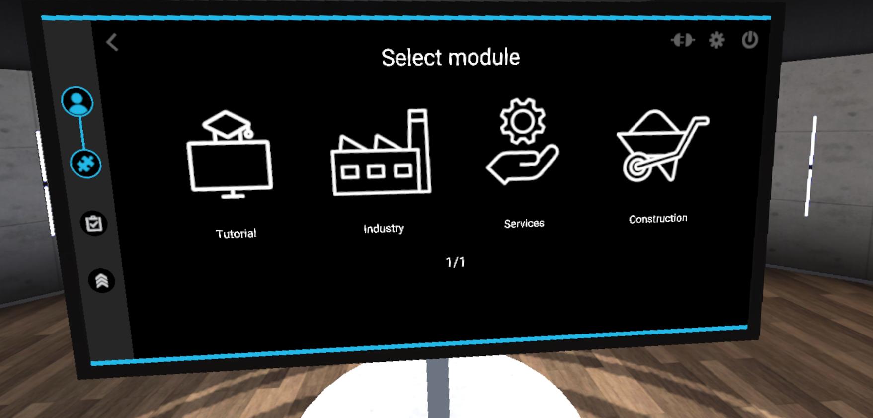
The available modules are "Building", "Industry", "Services" and "Tutorial". Pointing at a module allows see the description of the module, while clicking on a module will select it.
The tutorial allows you to familiarise yourself with the commands by running through a set of simple scenarios.
2.3.2. Selecting the exercise
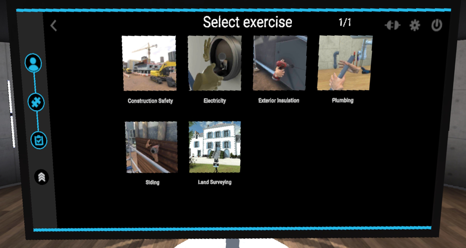
On this page, the exercises within the previously selected module are displayed. Pointing at an exercise displays a description of the selected exercise, while clicking on an exercise will launch it.
2.4. Watch
A watch appears on the user’s left controller, at wrist level. This watch will accompany the user throughout the exercise and provides guidance thanks to its 3 functions:

-
The compass: the needle marks the direction of the areas of interest for each stage of the exercise.
-
Timer: indicates the time elapsed since the start of the exercise.
-
Exit: The user can exit the exercise at any time by clicking on this button.
To interact with the buttons on the watch, point in their direction with your right hand. A laser is activated when the right hand approaches the watch. It allows you to interact with the buttons by clicking on the interaction button of the right hand controller.
2.5. Score screen
At the end of each exercise, the user is teleported back to the lobby to see a score screen showing the results of the exercise.
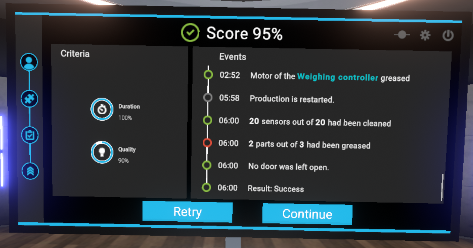
The score screen is organized as follows:
-
The score the user achieved in the exercise, as a percentage
-
Evaluation criteria for the exercise. The evaluation criteria are specific to each exercise
-
Events indicates the set of actions performed by the user, labeled with the time elapsed since the start of the exercise.
2.6. Tutorial
In order to familiarize the user with the available interactions, a tutorial scenario can be launched from the module selection menu.
The aim of the tutorial is to teach the user the commands of the virtual reality equipment and the different metaphors used in the application in a clear and progressive way. It will take place in a neutral and uncluttered environment so as not to distract the user from the various actions expected.
A panel detailing the association between the user’s controllers and the actions will always be visible during the experience.

The tutorial is presented in the form of successive themed rooms, which the user will have to perform one after the other:
-
Moving around
-
Grabbing and moving an object
-
Interacting with an object
In each of the rooms, the user will learn an action (i.e., use of a button) in a dedicated space, and then will have to put this action into practice to leave the room and move on to the next. Once the three rooms are completed, the user will go through a final door to finish the tutorial.
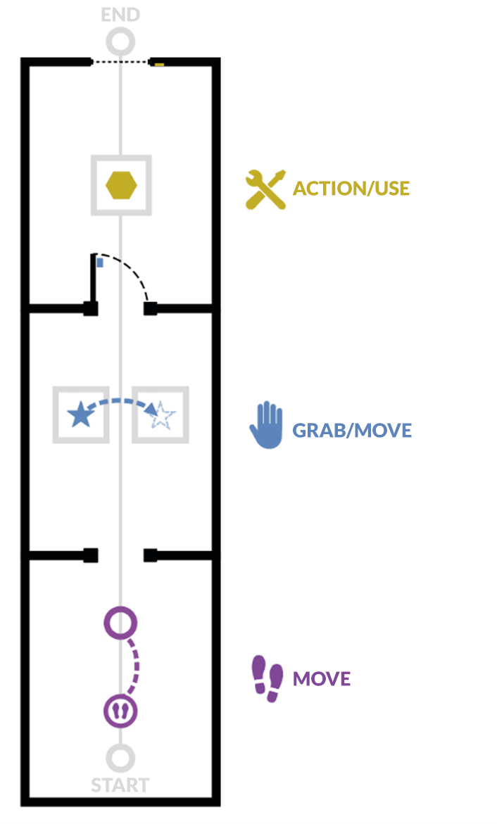
2.6.1. Moving
Objective: to learn how to move around the virtual world and recognize markers that indicate a specific location.
The user will learn to move by teleportation. To leave this first room, the user will be asked to teleport to the next room.
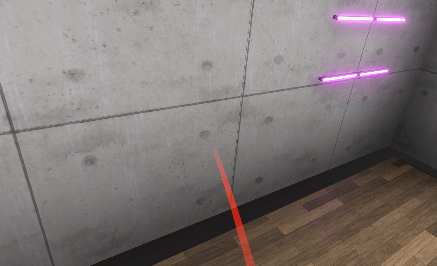
By pressing the "Teleportation" button, it is possible to initiate a teleportation. As long as the button is held down, you can choose the teleportation destination. When you release the button, the teleportation will be performed.
A parabolic pointer coming out of the controller will then be visible, symbolizing the path taken during a teleportation. If teleportation is possible, this pointer is violet; if not, it is red.

2.6.2. Picking Up/Moving an Object
Objective: To learn to pick up an object, release it and place it on a magnetized area, and to recognize the associated visual feedback.
The user will be invited to bring their hand close to an object, visualize the associated visual feedback (blue outline), then pick up the object using the associated button and drop it onto a designated area on a second display.
Once this action is completed, the user will be prompted to exit the room by opening a door, giving them the opportunity to use the "Grab an item" interaction again on the handle.

2.6.3. Action/Using a Tool
Objective: To learn how to interact with tools or buttons, and recognize the associated visual feedback.
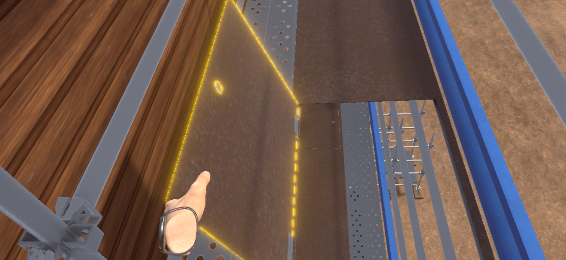
The user will be asked to interact with an object on a display (the object will be surrounded by a yellow outline indicating the possibility of activating it) and activate it using the associated button.
To exit the tutorial, the user will have to move to the back of the room and press the elevator button using the "Interact" button. A fade to black will return the user to the lobby.

3. Construction Module
3.1. Siding Installation
Situated in a building site environment, the user is presented with a building under construction where he will have to install wood siding on the façade. The user will have to access his workstation using the scaffolding, and install and fix the siding on the façade.
3.1.1. Exercise Plan
To complete the exercise, the user must carry out the actions in the following order:
-
Confirm the instructions at start-up
-
Use the ladder on the 1st floor
-
Open the 2nd floor hatch
-
Access the 2nd floor
-
Close the 2nd floor hatch
-
Take the 2nd floor ladder
-
Open the 3rd floor hatch
-
Access the 3rd floor
-
Close the 3rd floor hatch
-
Advance to the workstation
-
Grab the smallest board
-
Place the smallest board on the left side in the intended location
-
Grab the nail gun
-
Place the 3 nails in the intended locations on the smallest board using the nail gun
-
Grab the larger board
-
Place the larger board to the right of the first board in the intended location
-
Place the 5 nails in the intended locations on the larger board using the nail gun
3.1.2. Scenario flow
The user starts the scenario with the following briefing:
Siding
You must put the siding on the façade of the building in front of you. Use the scaffolding to get to your workstation on the 4th floor.
|
Tip
|
Remember to close the hatches after you have finished. |
To get to your workstation you will have to use the scaffolding and go to the 4th floor.

To use the ladder, the user uses the "Grab an object" button to climb and the "Interact" button to open the hatch.
|
Important
|
The user must close the hatches behind them to access the upper floors or risk having a penalty applied to their safety score. |
At his workstation, tools will be provided: a small and a large wooden board as well as a nail gun.

The user grabs and places the smallest board at the left end of the façade. They will have to take the nail gun in order to place the nails in the intended places using the "Interact" button. The user will not be able to proceed to the next step if a sufficient number of nails have not been placed. The user will then be able to place the second board, and perform the same operation.

Once the steps have been completed, the user will be teleported to the lobby in front of the scoring screen.
3.1.3. Criteria for evaluating the exercise
![]() Execution quality: Assesses if the boards are correctly placed and nailed
Execution quality: Assesses if the boards are correctly placed and nailed
![]() Safety: Assesses if the user has closed the hatches properly
Safety: Assesses if the user has closed the hatches properly
3.2. Electricity
This module will propose to the user to carry out some simple electrical operations: change a 220V socket, change the bulb of a wall lamp, and test the results of their work.
|
Note
|
The challenge of this module, in addition to carrying out the tasks requested, will be to carry them out in good safety conditions. Safety steps (such as putting on PPE or switching off the power) will not be explicitly suggested in the scenario thread, but the user will be reminded if they start to put themselves in danger. |
3.2.1. Exercise Plan
To complete the whole exercise, the user will have to carry out the actions in the following order:
-
Confirm the instructions at start-up
-
Grab the socket tester on the cart and test the two wall sockets (the socket at the end of the corridor is the faulty one)
-
Put on the gloves and helmet
-
Turn off the "Socket 1 corridor" or "General" circuit breaker on the electrical panel
-
Remove the defective socket
-
Remove the cables from the socket using the insulated screwdriver
-
Remove the defective socket
-
Grasp and replace the new socket
-
Screw in the cables of the socket
-
Replace with the new socket
-
Turn the power back on at the electrical panel
-
Test the new socket using the socket tester
-
Identify the faulty light fixture
-
Turn off the "hallway fixtures" circuit breaker.
-
Using the screwdriver, unscrew the 3 small screws on the cover of the wall light
-
Replace the defective bulb with a new one
-
Screw back the screws on the sconce cover
-
Turn the light back on at the electrical panel
3.2.2. Scenario flow
The user starts the scenario with the following briefing:
Electricity
As a maintenance electrician, you will have to change a defective outlet and change a light bulb in a wall light.
|
Tip
|
Don’t forget to follow safety procedures. |
Once the briefing is complete, the user is teleported to a corridor with two sockets (one functional, the other not) and two wall lights, one of which is defective. At the end of the corridor, a circuit breaker will be visible at the beginning of the scenario.
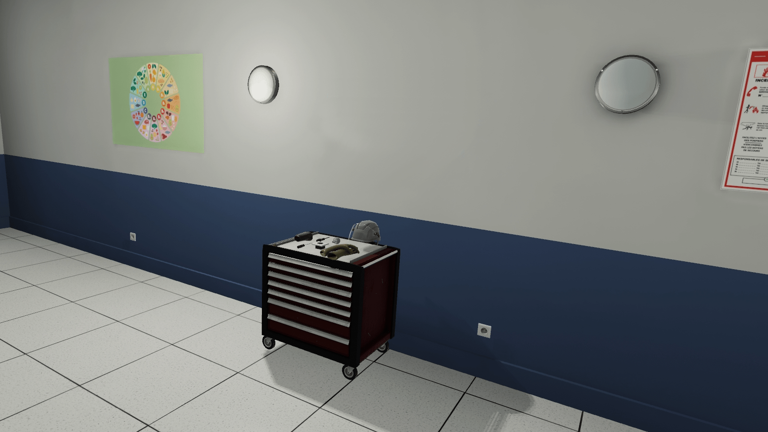
Their first task is to identify and replace the faulty socket. To do this, they grab the socket tester on the cart and check both wall sockets (by inserting the tester into the socket). The tester displays 230V if the tested socket is functional. If not, the tester displays OV.
Once the faulty socket has been identified, the user grabs the insulating gloves and helmet. To ensure safety, the user should turn off the circuit breaker ("Socket 1 corridor" or "General") before working on the socket.

They then go to the defective socket and detach it. In order to completely remove the plug, the user must loosen the screws on the 3 cables with the insulated screwdriver. The user can then pick up the defective plug and replace it with a new one.
The user then retightens the cable screws and installs the socket in the wall. Finally, the user switches the power back on to the sockets from the electrical panel and tests the replaced socket once again.
Their second task is to replace the bulb of the defective wall light. To avoid any risk of electrocution, the user must turn off the circuit breaker of the sconces from the electrical panel (they can turn off the "General" circuit breaker if they wish).

The user picks up the screwdriver and loosens the 3 screws of the defective light fixture’s cover. Once the cover is removed, they grab the bulb and replace it with a new one. The user can then replace the cover and screw it back on.
Before finishing, the user turns the power back on and checks that the light is working properly.
Once the steps have been completed, the user will be teleported to the lobby in front of the scoring screen.
3.2.3. Criteria for evaluating the exercise
![]() Execution quality: Assesses the change of the socket and the wall light.
Execution quality: Assesses the change of the socket and the wall light.
![]() Execution time: Evaluates the speed of the user to complete the intervention.
Execution time: Evaluates the speed of the user to complete the intervention.
![]() Safety: Assesses the safety conditions of the manipulations: PPE equipped, power off during manipulations.
Safety: Assesses the safety conditions of the manipulations: PPE equipped, power off during manipulations.
3.3. Exterior Insulation
In this scenario, the user will be asked to install and fix polystyrene insulation blocks and apply finishing plaster to a façade.
|
Note
|
In order to keep this module from being too repetitive, a number of actions will be automated: for example, the user will not have to lay all the polystyrene blocks, nor will they have to apply the plaster on the whole surface. Once a small area has been treated, the rest will be automatically filled in so that the scenario can continue. |
3.3.1. Exercise Plan
To complete the whole exercise, the user will have to carry out the actions in the following order:
-
Confirm the instructions at start-up
-
Pick up the metal rail on the workbench
-
Place the rail on the bottom of the front panel
-
Grab the insulation panel on the workbench
-
Place the insulation panel on the rail
-
Grab the drill from the workbench
-
Drill 5 holes on the provided locations
-
Grab the bolt on the workbench
-
Place 5 pegs on the drilled holes
-
Grasp the reinforcing fabric on the workbench
-
Lay three strips of canvas on the side
-
Use the ladder on the scaffolding
-
Open the trap door to access the second floor
-
Move to the work area
-
Grab the spray nozzle
-
Spray the plaster over the entire area to be treated
-
Confirm the action is complete by pressing "I’m done" on the instruction panel
-
Use the ladder on the scaffolding
-
Open the trap door to access the third floor
-
Move to the work area
-
Grab the scraper
-
Sweep the entire area to be treated with the scraper
-
Confirm the action is complete by pressing "I am done" on the instruction panel
3.3.2. Scenario flow
The user starts the scenario with the following briefing:
Insulator
You have to carry out the external insulation of a two-story building.
In order to carry out the task, the user will have the necessary materials available on the workbench to their right at the start of the exercise.
The user grabs a rail, and comes to place it on the "ghost" of its final position. It will not be necessary to screw the rails down. The user will have to do the operation once to treat the whole length of the façade.

Once the rails have been laid, the user will need to grab an insulation panel from the workbench. The drop zone is highlighted on the front; the user drops the panel onto the zone.
The user takes the drill on the workbench, and drills 5 holes in the panel at the designated locations by pressing the "Interact" button near the areas.
The user grabs the roll of reinforcing fabric, and applies it to a first area at the bottom of the façade by pressing the "Interact" button. A strip appears on the whole height of the building. The user repeats the operation twice.

The user uses the scaffolding ladder to access the first floor.
They grab the spray nozzle to spray plaster over the entire area required by sweeping the area while holding the "Interact" key.
Once the area has been treated, they must confirm their action by clicking on the "I’m done" button on the instruction panel.

The user then uses the ladder to access the 2nd floor. They grab the scraper and applies it to the entire area required.
Once the area has been treated, the user must confirm his action by clicking on the "I’m done" button on the instruction panel.

Once the steps have been completed, the user will be teleported to the lobby in front of the scoring screen.
3.3.3. Criteria for evaluating the exercise
![]() Execution quality: Evaluates the percentage of surface covered during plastering and scraping.
Execution quality: Evaluates the percentage of surface covered during plastering and scraping.
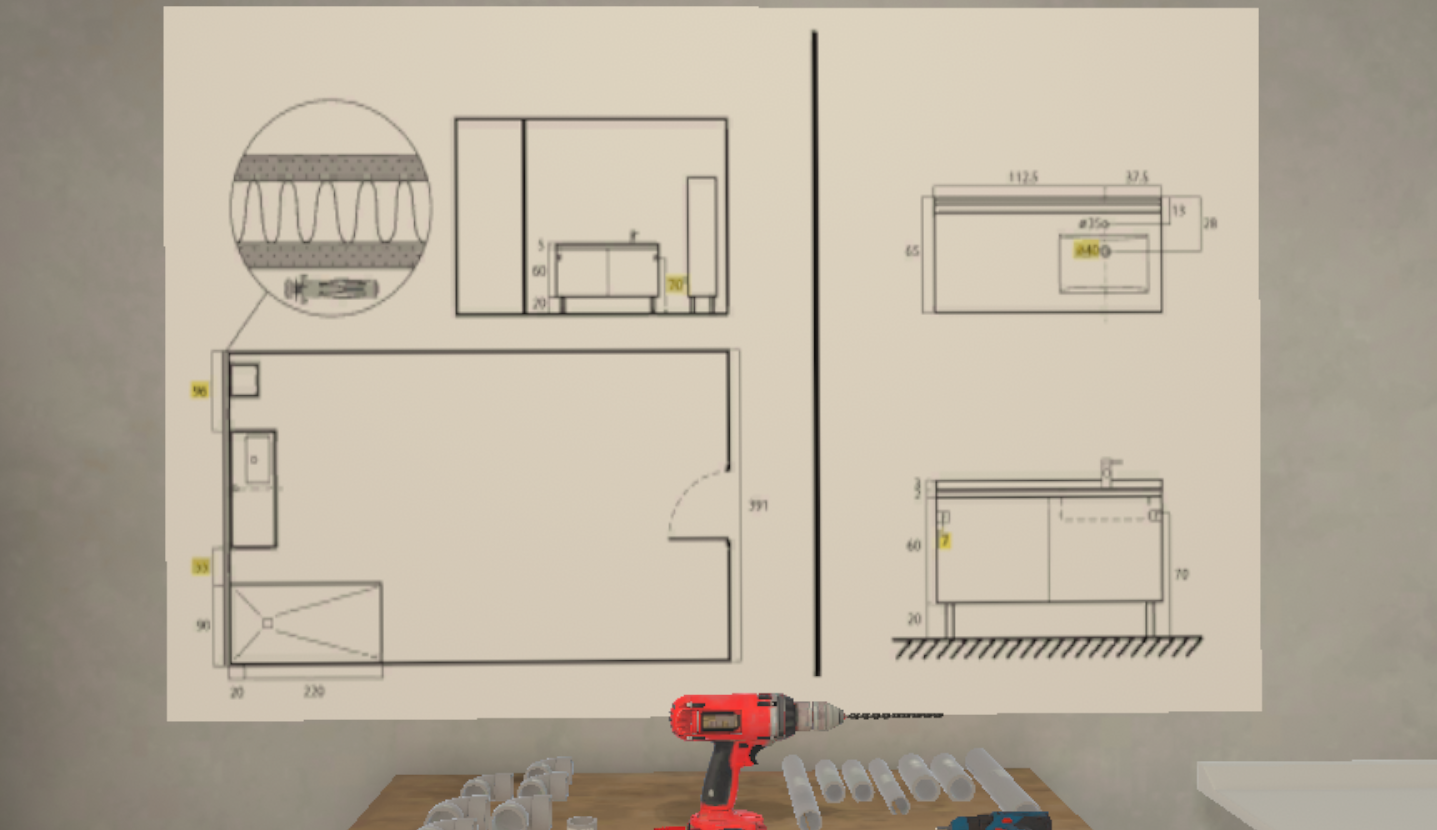
3.4. Plumbing
This module will allow the user to install a cabinet and a sink in a bathroom that is being renovated.
|
Note
|
The user will be assessed on their ability to place the cabinet and sink in a way that is functional but also conforms to the blueprints. |
3.4.1. Exercise Plan
To complete the whole exercise, the user must carry out the actions in the following order:
-
Confirm the instructions at start-up
-
Consult the blueprints and identify the locations of the two holes to be drilled
-
Grab the drill on the workbench and drill the holes
-
Grab the molly bolts and place them in the holes
-
Grab the cabinet and place it in the correct location
-
Grab the cordless screwdriver and screw the cabinet in place
-
Grab the sink and place it on top of the cabinet
-
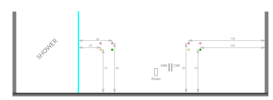
Connect the flexible hoses of the mixer tap to the hot water inlet and the cold water inlet
-
Grab the Ø50 - Ø40 reducer and place it on the tube coming out of the wall
-
Select the L150 Ø40 pipe and place it on the fitting
-
Select the Ø40 elbow and place it at the end of the previously placed pipe
-
Select the L350 Ø40 pipe and place it at the end of the previously placed pipe
-
Test the assembly by operating the faucet
3.4.2. Scenario flow
The user starts the scenario with the following briefing:
Plumbing
Your mission consists of placing a sink and cabinet in a bathroom being renovated.
|
Tip
|
Carefully follow the plans above your workbench. |
Once the briefing has been accepted, the user is teleported to a bathroom being renovated. In this room there is a workbench with the tools needed for the job, a sink, a cabinet and an assembly plan.
The user’s first task is to install the cabinet unit.
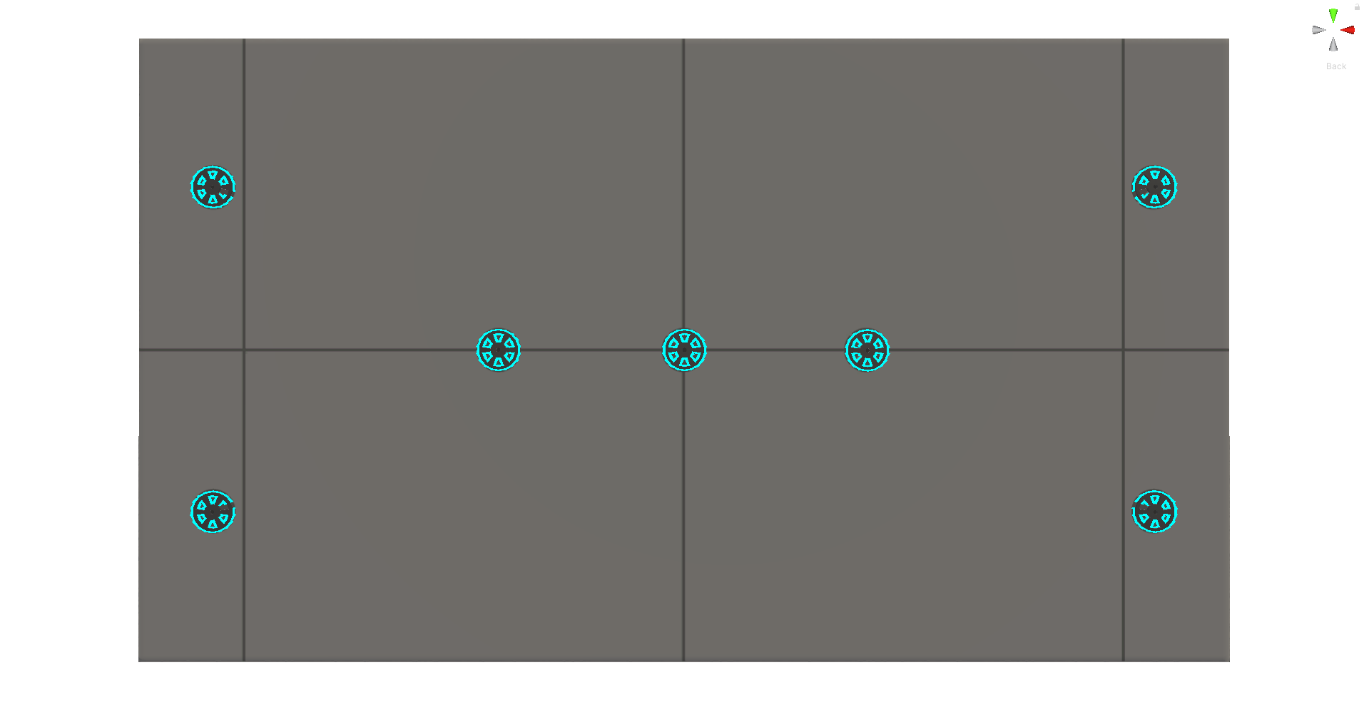
With the help of the assembly plan on the wall, the user must determine the position of the cabinet and drill two of the eight holes on the wall using a drill.
Once the holes have been drilled, the user selects the correct anchor for the wall and places the anchor in the holes.
The cabinet can then be placed on its location.
Using the cordless screwdriver, fasten the furniture to the wall.
With the cabinet installed, pick up the sink and place it on top of the cabinet.
The faucet and its hoses are already mounted on the basin.
The user will need to grasp the end of the hot and cold water hoses and connect them to the correct water supply.
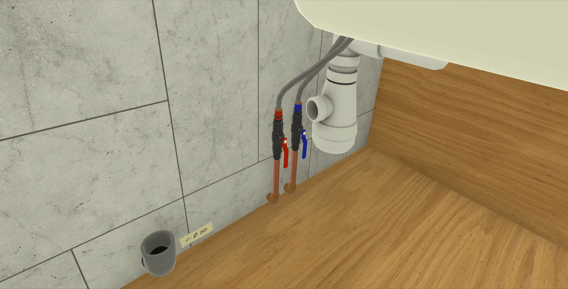
The next step is to connect the sink’s drain pipes.
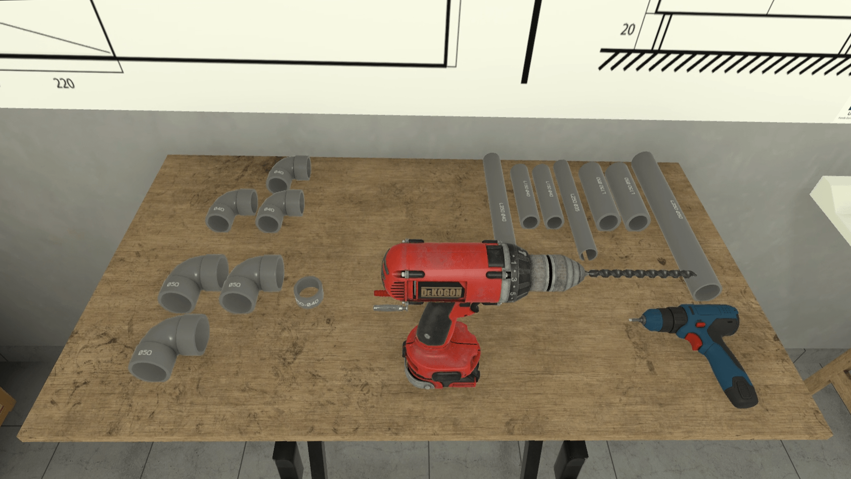
As the wall-mounted drain is 50mm diameter, the user should place the Ø50-Ø40 reducer in the elbow to reduce the diameter to 40mm.
They then take the L150 Ø40 pipe and inserts it on the reducer.
They then place the Ø40 elbow at the end of the previously laid pipe.
Finally, they place the L350 Ø40 pipe between the last pipe laid and the sink’s drain.
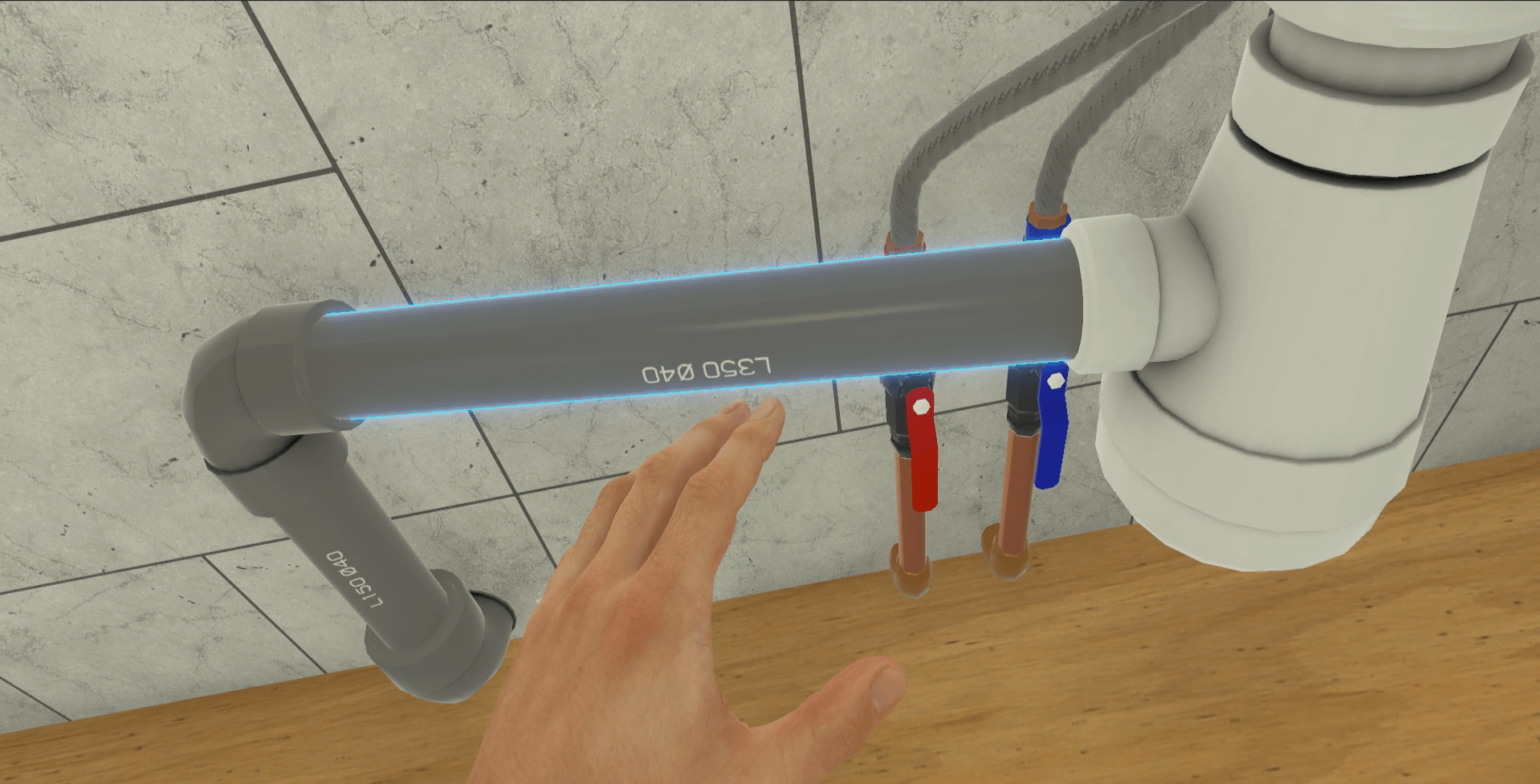
In order to complete the exercise, the user will have to test their assembly by operating the faucet.
Once the steps have been completed, the user will be teleported to the lobby in front of the scoring screen.
3.4.3. Criteria for evaluating the exercise
![]() Quality of Execution: Evaluates the functionality of the assembly.
Quality of Execution: Evaluates the functionality of the assembly.
![]() Compliance with Plan: Evaluates how closely the assembly conformed to the proposed plan.
Compliance with Plan: Evaluates how closely the assembly conformed to the proposed plan.
![]() Execution time: Evaluates the speed of the user in completing the tasks requested.
Execution time: Evaluates the speed of the user in completing the tasks requested.
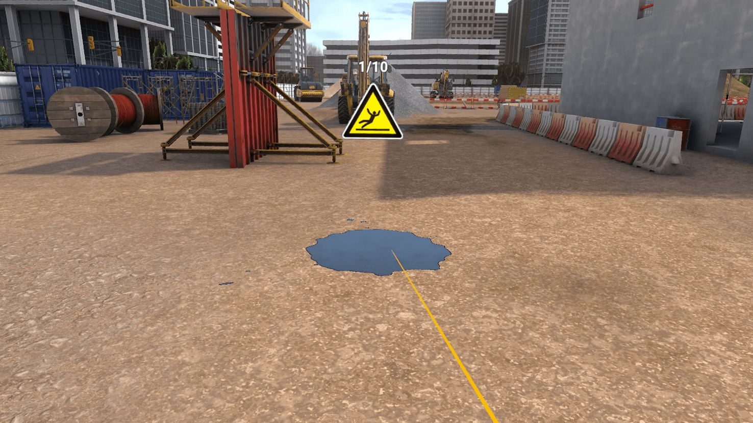
3.5. Site safety
This exercise makes the user aware of the dangers that can be encountered on a construction site.
3.5.1. Objective of the exercise
The user starts the scenario with the following briefing:
Construction site safety
Walk around the construction site and identify dangerous situations.
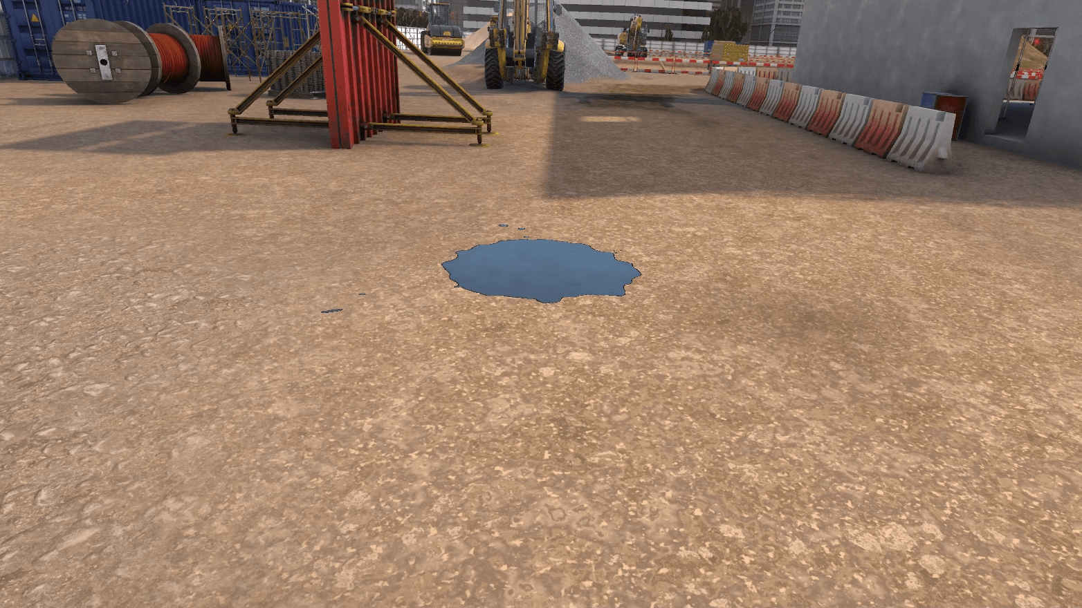
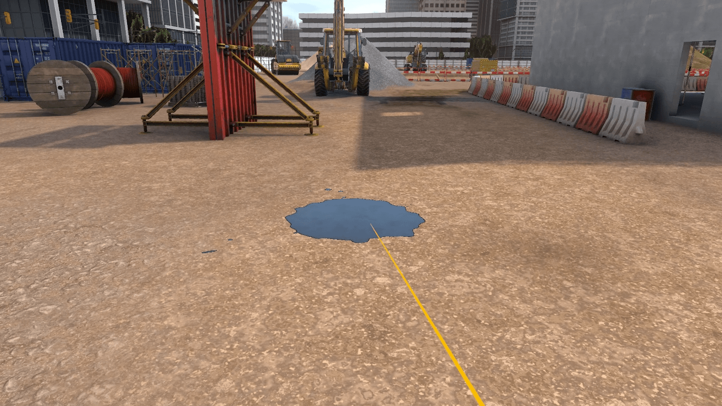
Once the briefing has been accepted, the user can move freely around the entire site.
Hazards are scattered throughout the site and a fatal error occurs if the user gets too close to a hazard. The user will complete the exercise when they have identified 10 hazards.
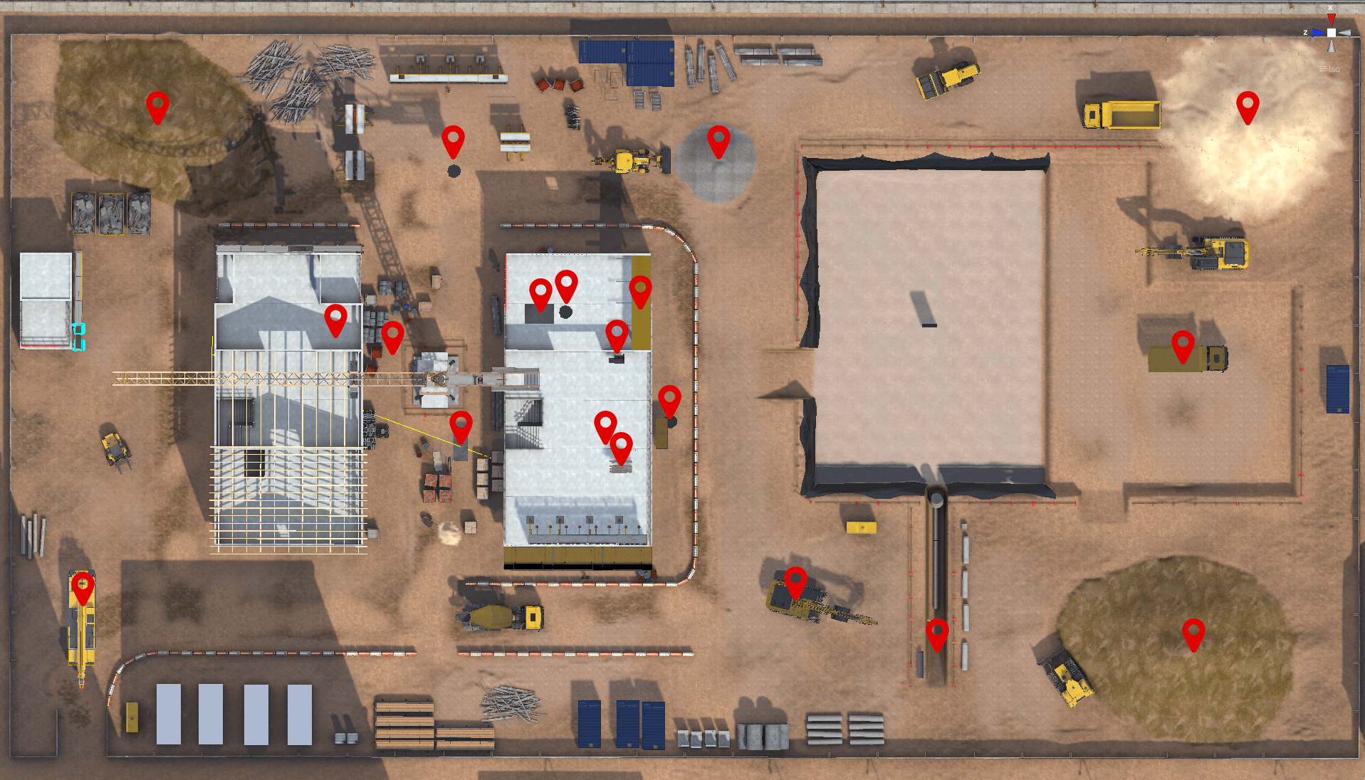
In this mode, the user does not have the option of securing the hazards they encounter, and can exit the exercise at any time by clicking on the cross on the watch on their left wrist.
3.5.2. Criteria for evaluating the exercise
![]() Execution time: Evaluates the user’s speed in completed the requested tasks.
Execution time: Evaluates the user’s speed in completed the requested tasks.
![]() Execution identification : The ability of the user to identify the number of hazards requested.
Execution identification : The ability of the user to identify the number of hazards requested.
3.6. Surveyor
The user acts as a surveyor in this three-step scenario. First, they will scan a mansion to collect data using a 3D scanner. Then, they will process this information in their office, in the form of a puzzle. Finally, they will check the data by projecting it on a model of the building to find the scanning errors.
3.6.1. Exercise Plan
To complete the exercise, the users will have to proceed with the actions in the following order:
-
Launch a scan.
-
In the scanner interface, click on the arrows to observe the scan from all angles.
-
Move the scanner to the indicated area.
-
Start a scan.
-
Place the scanner freely. Move the scanner to scan the entire building, with as few activations as possible.
-
Recover the data from the field to combine them and transform them into a geolocalized digital model.
-
In order to reconstruct the building, grab the pieces to combine them together on the plan, like a 3D puzzle. On the workstation screen, click on the arrows to scroll through reference photos to help you.
-
Using the photographic references, locate any errors (missing windows, wall colors, etc.) on the exterior of the building and point them out and press the "action" button.
3.6.2. Scenario sequence
The scenario is divided into 3 parts.
Data acquisition (1/3)

The goal of this phase is to acquire data by scanning a building. The user is in front of a mansion with a 3D scanner. After confirming the instruction panel, the user must launch a first scan using the tablet placed on the scanner’s stand.
|
Note
|
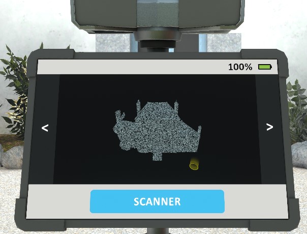
Figure 37. Scanner interface
The user can interact with the scanner interface. They can click on the "Scanner" button to start a scan. The map on the tablet is updated to show the scanned area and the position of the scanner when it is activated, using a yellow circle. They can click on the arrows on the left and right to observe the scan from all angles. At the top right is the battery indicator. |
Once the button is pressed, the 3D scanner rotates 360° on itself, emitting a sound signal, and the map is updated.
The user must observe the scan from all angles in the scanner interface by clicking on the arrows.
The user is then asked to pick up the scanner, and drop it on the area indicated by an icon, a few meters away. Once the scanner is dropped in the proposed area, the user is asked to make a new scan, which updates the map.
Once this second scan is done, the user is now free to continue the scan without further assistance.
From this step, the battery of the device will progressively decrease to act as a time counter (3 minutes). At 30 seconds from the end of the counter, the battery indicator will start to flash and the 3D scanner will emit a beep. When the battery is depleted, the data acquisition stage ends automatically.
If the user has scanned at least 3x and is satisfied with their work, they can end this sequence prematurely by clicking the "Skip this step" button on the instruction panel.
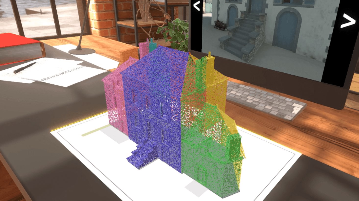
Data processing (2/3)
The user is presented with a desk equipped with a workstation. A paper plan, representing the footprint of the building, is placed on the desk between the user and the screen. The instruction panel displays the following message:
Data Processing
As an office survey technician, you must retrieve data from the field to combine and transform it into a geolocated digital model.

On the desktop, 7 clouds of points of different colors are arranged on the right of the map. The user has to grab the pieces to combine them together like a 3D puzzle to rebuild the building.
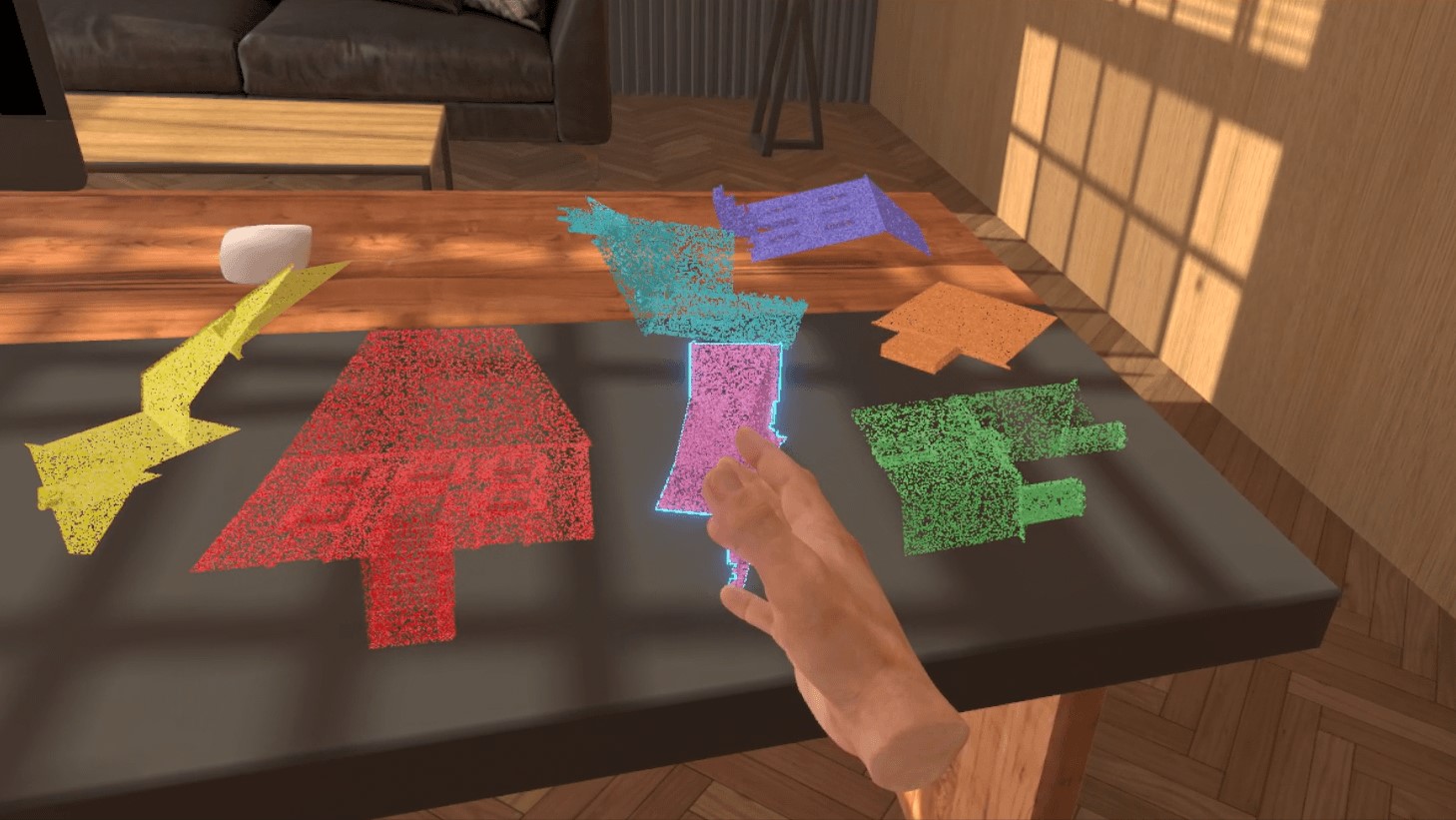

When the user, with the help of reference photos available on the workstation screen, places a part in the correct location on the plan, a success sound will play and it will not be possible to move that part again.

At any time, the user will be able to complete their work by pressing the "Skip this step" button on the instruction screen. This action will move the scenario to the next phase.
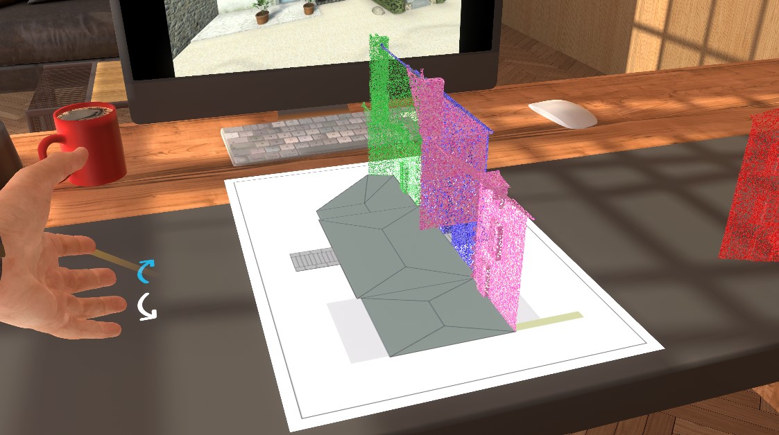
Verification of the Model (3/3)
To complete the scenario, the user is presented with the BIM model of his building scan. The instruction panel displays the following message:
Verification of the Model
As a surveyor, you need to make sure that the building model matches perfectly.
Using the photo references, locate any errors (missing windows, wall colors, etc.) on the outside of the building and point them out and press the "action" button.
From 1 to 3 errors will be randomly generated on the model, which the user must find. In order to make this step feasible for the general public, these errors will be fairly easy to spot.
To mark a defect, the user will point to an element which will automatically activate a laser in the extension of his hand. The element will then be highlighted with a yellow color effect, and the selection can be validated via the "action" button. If the selected element had a defect, it is substituted and colored in green. Otherwise, it flashes red for a few moments, then an error sound will play.


Here are images showing the house, without scanning errors, from several angles:


And here are the 12 possible scan errors, which the player must spot:


To help the player spot errors, several points of interest float around the house. The user can grab these photographs and position them as they wish, while checking the model.

The user will be able to enter the house and visit the second floor. Symbolic furniture will be present, with an aesthetic close to the digital model. No mistakes are made inside the house.

Once the user points to an element, he can validate the model using the "Skip this step" button on the instruction screen, which will end the exercise. If the user finds all the errors, the exercise ends automatically.
Once the exercise is finished, the user will be teleported to the lobby in front of the scoring screen.
3.6.3. Exercise Evaluation Criteria
![]() Quality of Collected Data: Evaluates the percentage of the building scanned
Quality of Collected Data: Evaluates the percentage of the building scanned
![]() Survey Optimization: Evaluates the number of scanner activations (the scan must be done in a minimum number of tries)
Survey Optimization: Evaluates the number of scanner activations (the scan must be done in a minimum number of tries)
![]() 3D Vision : Evaluations the time of completion and the accurace of the puzzle
3D Vision : Evaluations the time of completion and the accurace of the puzzle
![]() Error Search : Evaluates the number of inconsistencies found by the user and the errors made by the user
Error Search : Evaluates the number of inconsistencies found by the user and the errors made by the user
3.7. Masonry
In this scenario, the user will complete the construction of a wall by laying the final course of concrete blocks. They will be instructed to spread a layer of mortar on the wall and then set the blocks in place, ensuring proper alignment.
This exercise evaluates the user’s ability to follow a defined procedure and perform each step accurately.
3.7.1. Exercise Plan
To complete the exercise successfully, the user must perform the following actions:
-
Confirm the startup instructions.
-
Pick up the mortar applicator roller.
-
Position the roller at a 25-degree angle on the highlighted course of concrete blocks.
-
Maintain the angle while moving the roller along the course to spread the mortar evenly.
-
Place the appropriate block at the end of the course next to the door opening.
-
Use the level and mallet to align the block.
-
Place the appropriate block at the beginning of the course.
-
Use the level and mallet again to align the block.
-
Stretch the mason’s line (chalk line) above one of the two previously placed blocks.
-
Complete the course by laying the remaining blocks, alternating placement from each side and checking alignment and level.
-
Confirm completion of the wall in the instruction interface.
3.7.2. Scenario Flow
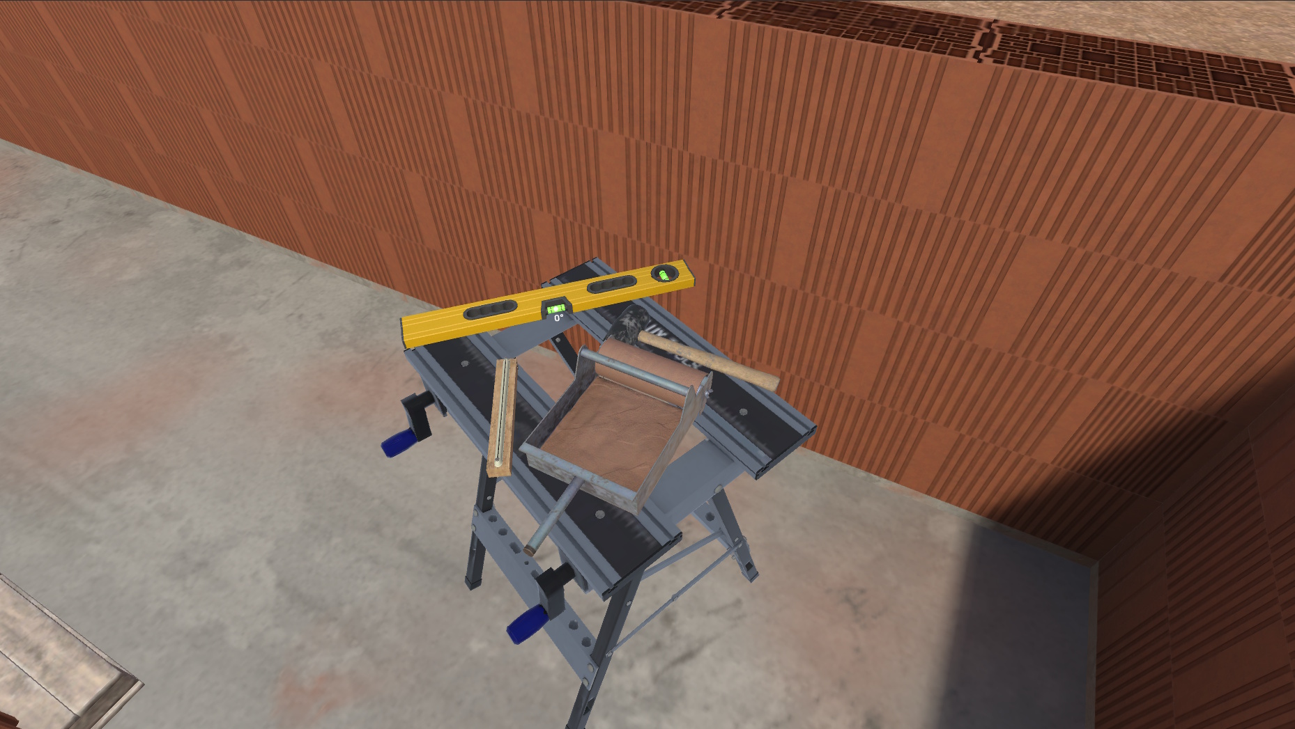
The scenario begins on an active construction site. In front of the user is a control screen used to start and complete the exercise.
All the tools needed to perform the exercise are placed on the sawhorse in front of the user.
-
A mortar applicator roller
-
A level
-
A mallet
-
A mason’s line
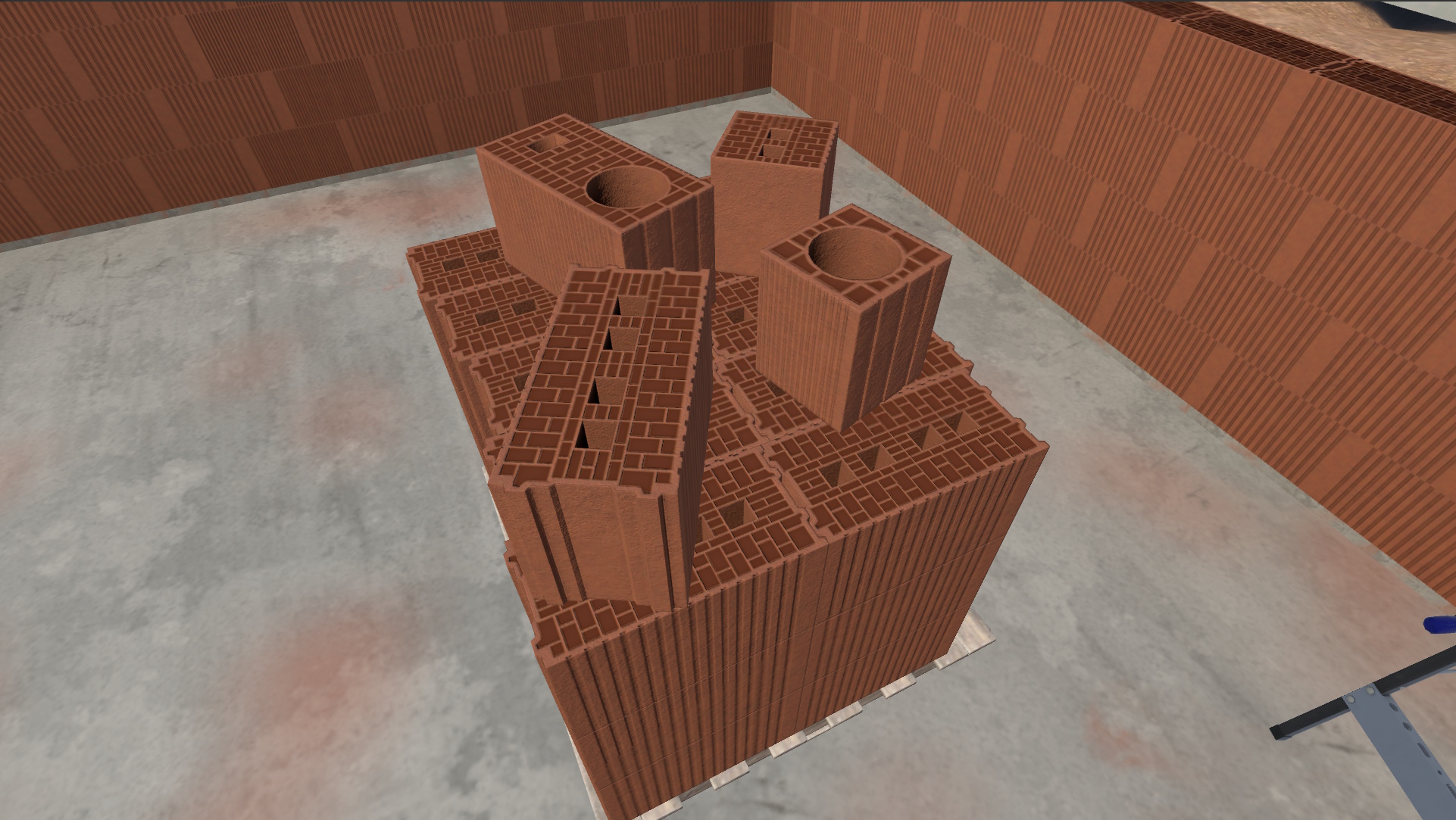
The concrete blocks are stacked on the pallet to the left. There are four types:
-
A standard block
-
A standard block with an opening, used for door or window frames
-
A half block
-
A half block with an opening, used for door or window frames
|
Note
|
For this exercise, only the standard blocks and one half block with an opening will be required. |
After reviewing the environment and the briefing, the user must complete the unfinished wall to their right.
Click the Start button to begin the task.
First, apply the mortar using the applicator roller. To do this, pick up the roller and apply mortar along the top edge of the wall.
Be sure to cover the entire area with mortar before proceeding to the next step.
|
Important
|
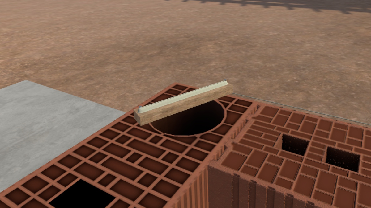
The mortar applicator roller must be held at a 25° (+/-5°) angle relative to the wall. 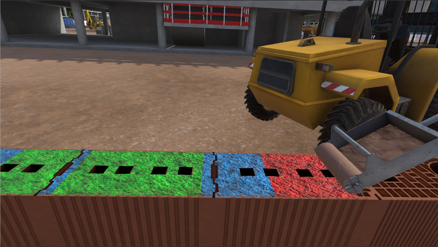
Figure 64. Overview of Mortar Application
|
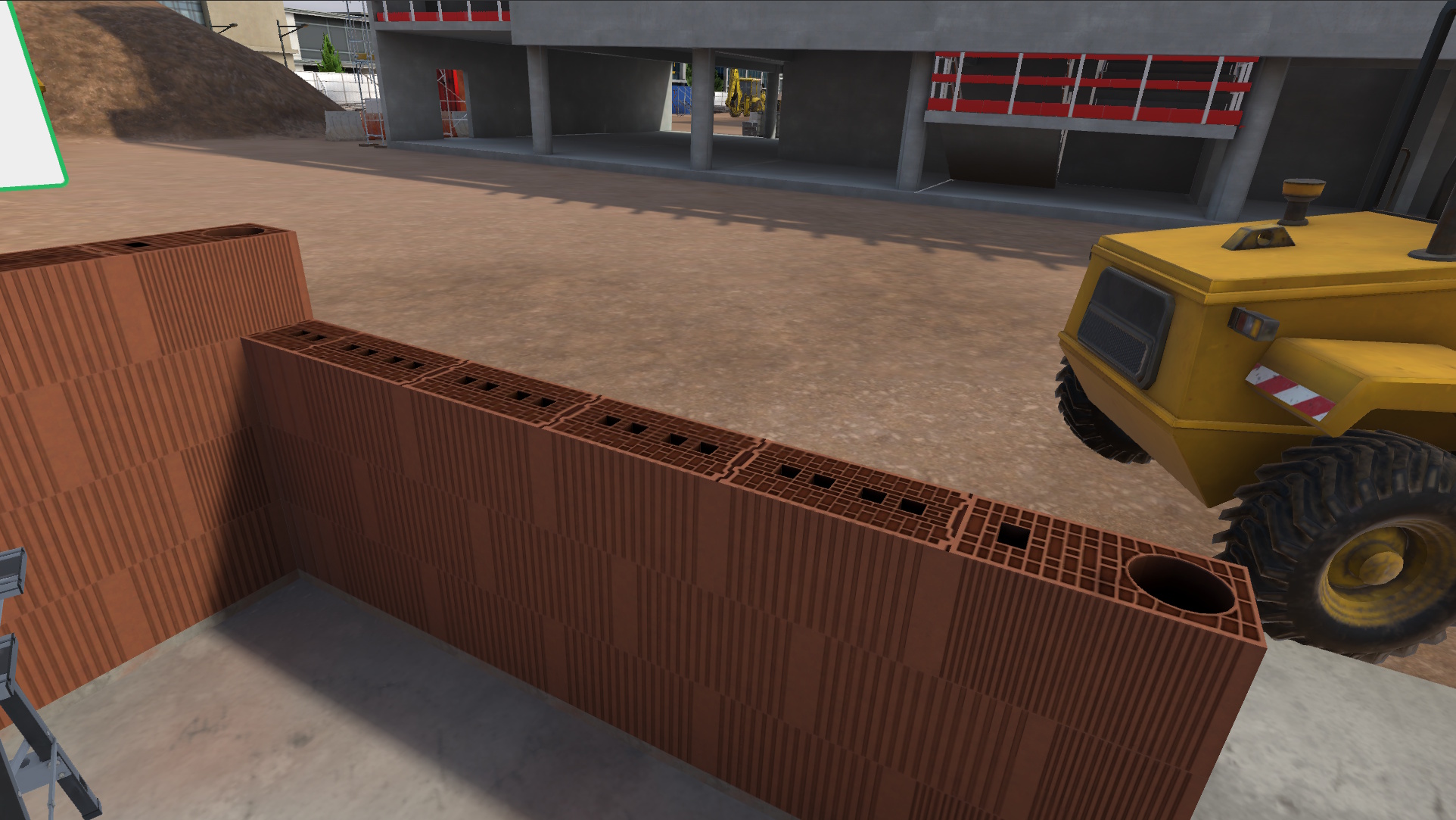
When all the mortar has been applied, take a half block with an opening and place it beside the doorway.
It will initially not be level; use the mallet and the level to check and adjust its alignment.
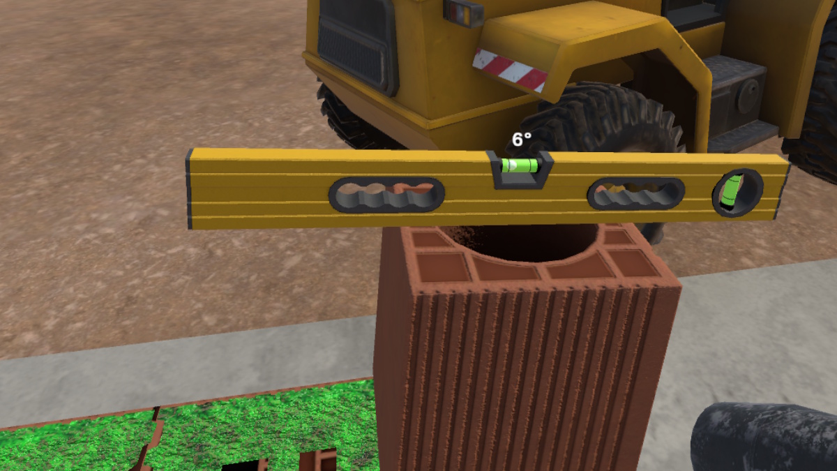
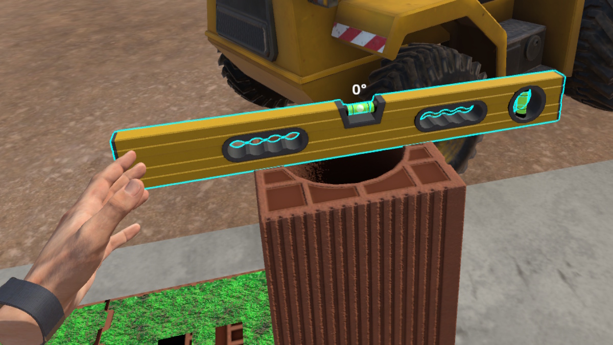
Repeat this process with a standard block on the opposite side of the course.
Place the mason’s line over one of the two blocks positioned earlier.
Continue placing the remaining blocks to complete the wall.
|
Note
|
The blocks should be laid in an alternating pattern, one after the other. 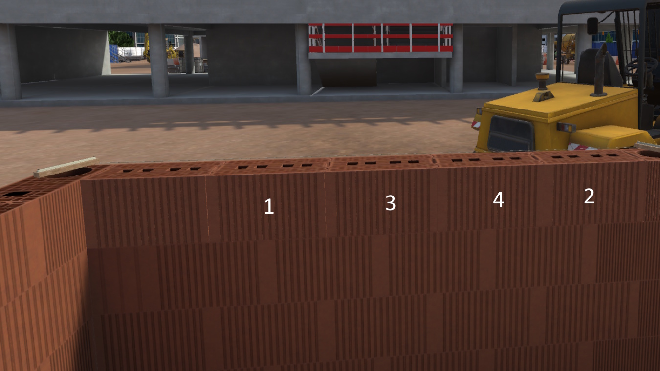
Figure 68. Guidelines for block placement
|
When the wall is complete, the user must click the Finish button in the interface.
3.7.3. Evaluation Criteria
![]() Quality of Execution: Evaluates the thickness of the mortar and the final alignment of the blocks.
Quality of Execution: Evaluates the thickness of the mortar and the final alignment of the blocks.
![]() Procedural Compliance: Assesses block selection, application method, and verifies that the course is fully completed.
Procedural Compliance: Assesses block selection, application method, and verifies that the course is fully completed.
4. Industrial Module
4.1. Line Operator
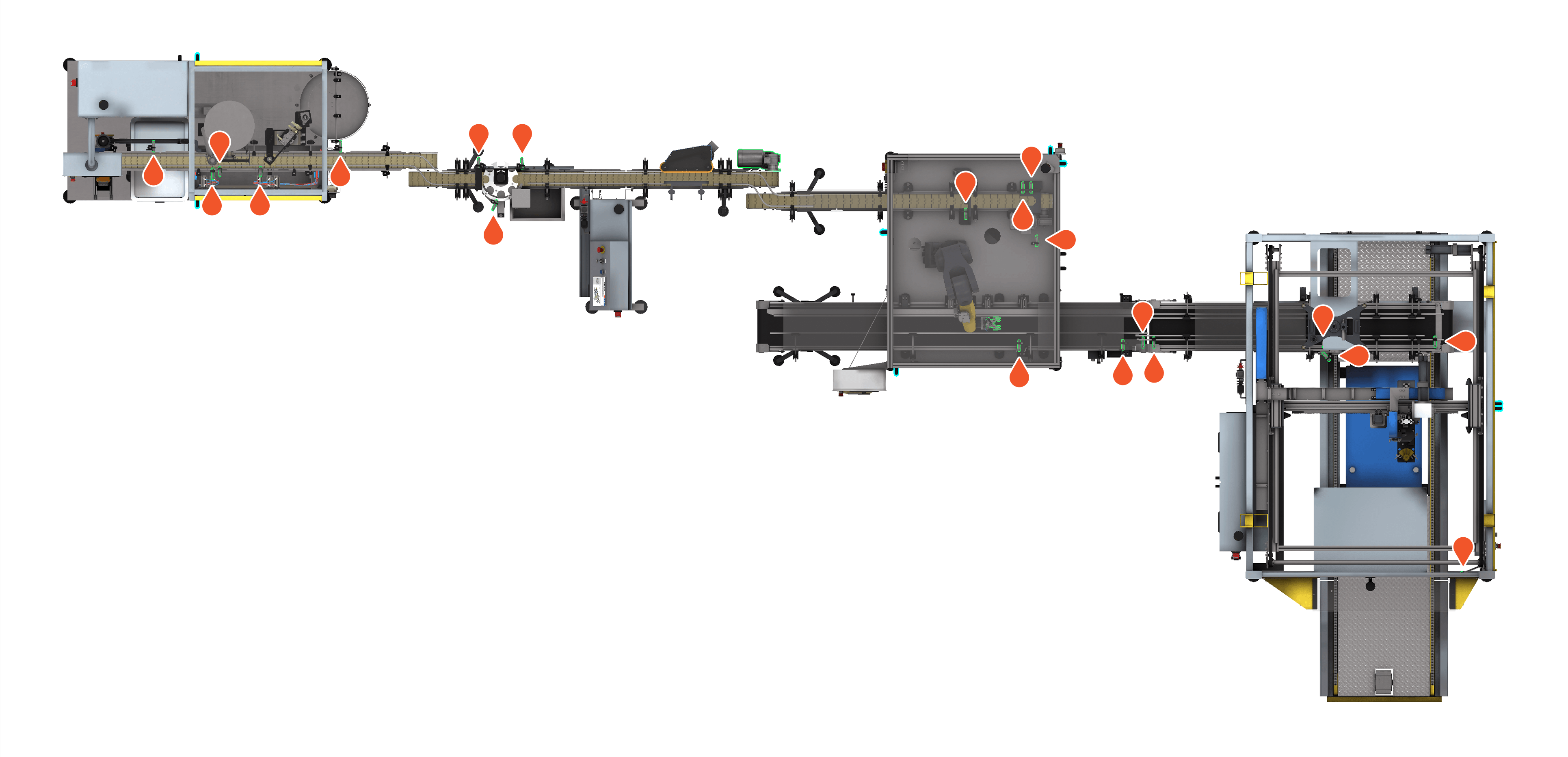
During the scenario the user will be asked to carry out maintenance operations on a production line. They will be asked to clean the sensors of a production line and to grease several parts.
This module will evaluate the user’s sense of observation and their ability to carry out the required operations in a limited time.
4.1.1. Exercise Plan
To validate the whole exercise, they must carry out the actions in the following order:
-
Confirm the instructions at start-up
-
Consult the screen for the tasks to be performed
-
Grab the cloth from the table
-
Pass the cloth over the 20 sensors
-
Grab the degreaser
-
Grease the axles
-
Grease the motor of the weighing control
-
Grease the clamp of the articulated arm
-
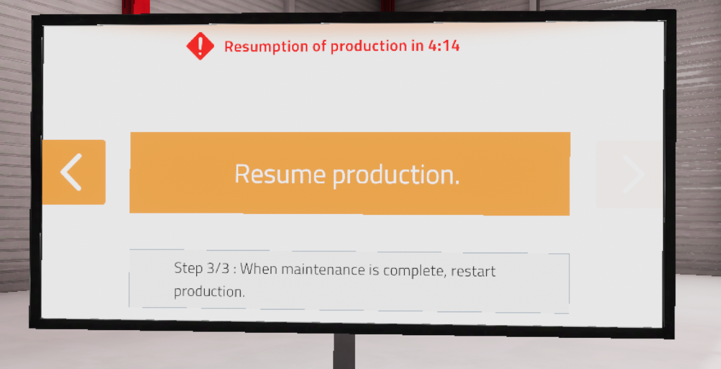
Click on "Resume production"
4.1.2. Scenario flow
The user starts the scenario with the following briefing:
Line Operator
Your task will consist of carrying out the daily maintenance operations of the production line before its start-up. Refer to the screen to find the tasks' details, and when finished, validate them in order to resume production.
|
Tip
|
The necessary tools are on the table. Don’t waste time: production must start as soon as possible! |
The scenario will start in a hangar with a complete production line switched off. The nearby screen will show the maintenance operations and the time remaining before production starts. It is also on this screen that the user can use to end the exercise.
The necessary tools (rag and pressurized grease can) will be placed on a table in the user’s field of vision.
The user will have to consult the screen in order to learn about their tasks.
Their first task is to identify and clean the 20 sensors hidden throughout the production line.

The user will need to grab the cloth on the nearby table, locate and clean the sensors on the line.
|
Important
|
Some sensors will require doors to be opened. The user will have to click on the door handles to open them. |
Once the 20 sensors have been cleaned, his second task will be to grease some of the components of the production line.
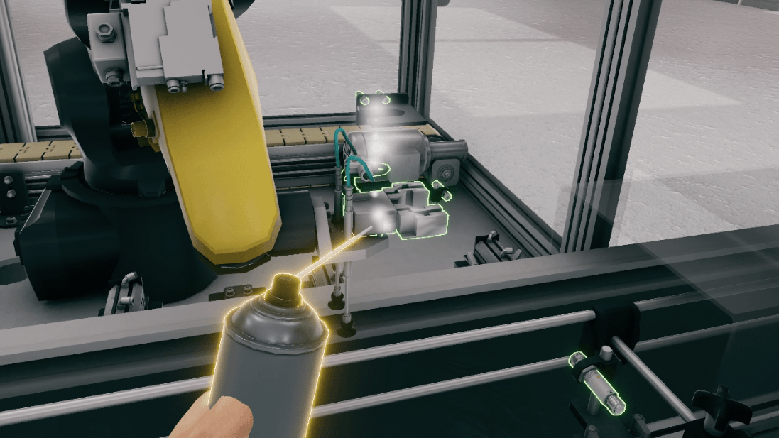
The user will have to grab the degreasing spray and use it with the "Interact" button on the three elements in the picture.
-
Weighing control wheel axis
-
Weighing control motor
-
Base of the articulated arm
Once the parts have been greased, the user should return to the screen and click on the "Resume Production" button, which will end the countdown and the exercise. The user is then teleported back to the lobby to the scoring screen.
4.1.3. Criteria for evaluating the exercise
![]() Execution quality: Evaluates the ability of the user to clean and grease all the requested elements
Execution quality: Evaluates the ability of the user to clean and grease all the requested elements
![]() Execution time: Evaluates the speed of the user in completing the requested tasks.
Execution time: Evaluates the speed of the user in completing the requested tasks.
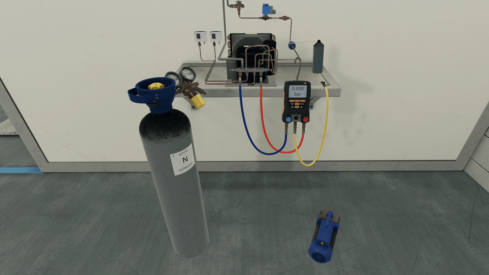
4.2. Refrigerant
Working in a warehouse, the user will have to carry out a leak test of a refrigeration circuit in a cold room by pressurizing the circuit.
4.2.1. Exercise Plan
To complete the whole exercise, the user must carry out the actions in the following order:
-
Confirm the instructions at start-up
-
Grab the yellow hose from the pressure gauges
-
Connect the yellow gauge hose to the nitrogen regulator
-
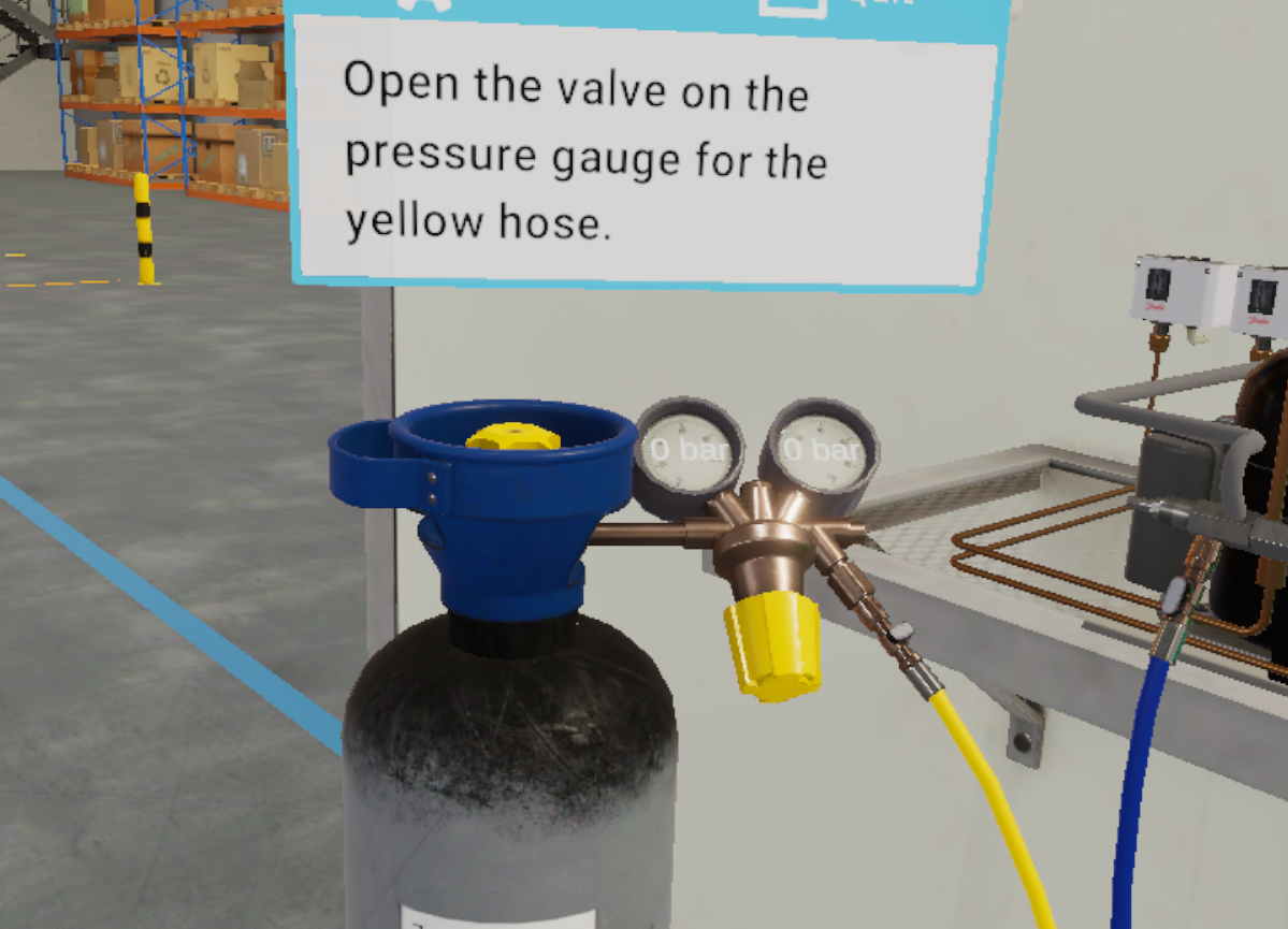
Open the valve on the yellow pressure gauge hose
-
Open the nitrogen cylinder
-
Set the output pressure
-
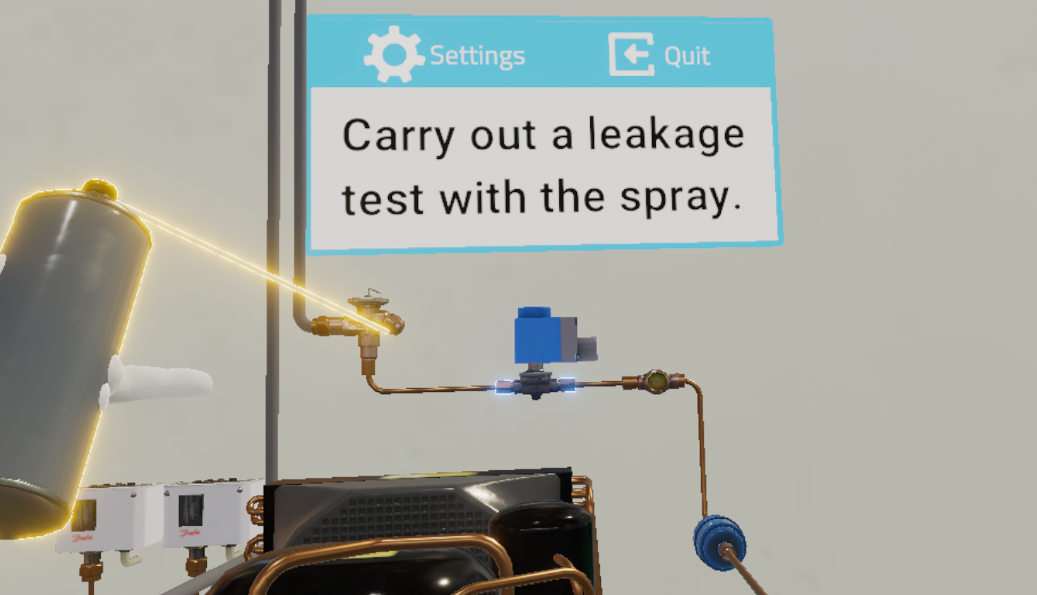
Grasp the spray and check for leaks
-
Confirm that there are no leaks
-
Close the nitrogen bottle
-
Close the yellow hose of the pressure gauges
-
Open the valve on the yellow hose to release the nitrogen
-
Grab the yellow hose from the pressure gauges
-
Connect the yellow hose to the vacuum pump
-
Press the yellow button on the vacuum pump to start it
-
Turn off the vacuum pump when the pressure in the gauges has dropped
-
Close the valve on the yellow hose of the pressure gauges
4.2.2. Scenario flow
The user starts the scenario with the following briefing:
Refrigerant
After changing a solenoid valve, you will have to perform a leakage test.
At the start of the scenario, the user is presented with a refrigerant circuit and the tools needed to carry out the task: a nitrogen cylinder, pressure gauges, a leak detection spray and a vacuum pump.
The first step of the exercise will be to fill the nitrogen circuit using the pressure gauges.
First, the user connects the yellow hose from the pressure gauges to the regulator on the nitrogen cylinder and opens the valve on the hose.
To put the nitrogen into the system, the user will need to open the nitrogen cylinder and adjust the pressure.
The pressure regulator on the cylinder will then show 100 bar at the inlet and 20 bar at the outlet. Note also that the pressure gauges will read 20 bar.
|
Note
|
Interactive elements such as valves, caps and switches will be highlighted in yellow to better guide the user. |
The circuit is then filled, so the user proceeds to the leak test on the previously replaced part.
Using the spray, the user sprays the liquid on the connections of the part (these connections will be highlighted) to identify the presence of a leak. The user will then have to report his findings on the instruction panel by answering "No" to the question asked.
At the end of the leakage test, their mission is to empty the nitrogen from the circuit.
To do this, they will have to stop the gas circulation by closing the nitrogen bottle and the yellow hose of the pressure gauges, disconnect the yellow hose and open the valve of the hose to release the nitrogen. The pressure gauges will then indicate 0 bar of pressure.
Finally, they use the vacuum pump to completely drain the nitrogen from the system.
They should then connect the yellow hose to the vacuum pump, turn on the vacuum pump.
When the pressure indicated on the manometers is lower than -0.63 bar, they should close the valve of the yellow hose and turn off the vacuum pump.
Once the mission is completed, the user will be teleported to the lobby in front of the scoring screen.
4.2.3. Criteria for evaluating the exercise
![]() Execution quality: Evaluates the user’s ability to follow the pressurization process, and their response to the question asked during the exercise.
Execution quality: Evaluates the user’s ability to follow the pressurization process, and their response to the question asked during the exercise.
![]() Execution time: Evaluates how quickly the user completes the tasks requested.
Execution time: Evaluates how quickly the user completes the tasks requested.
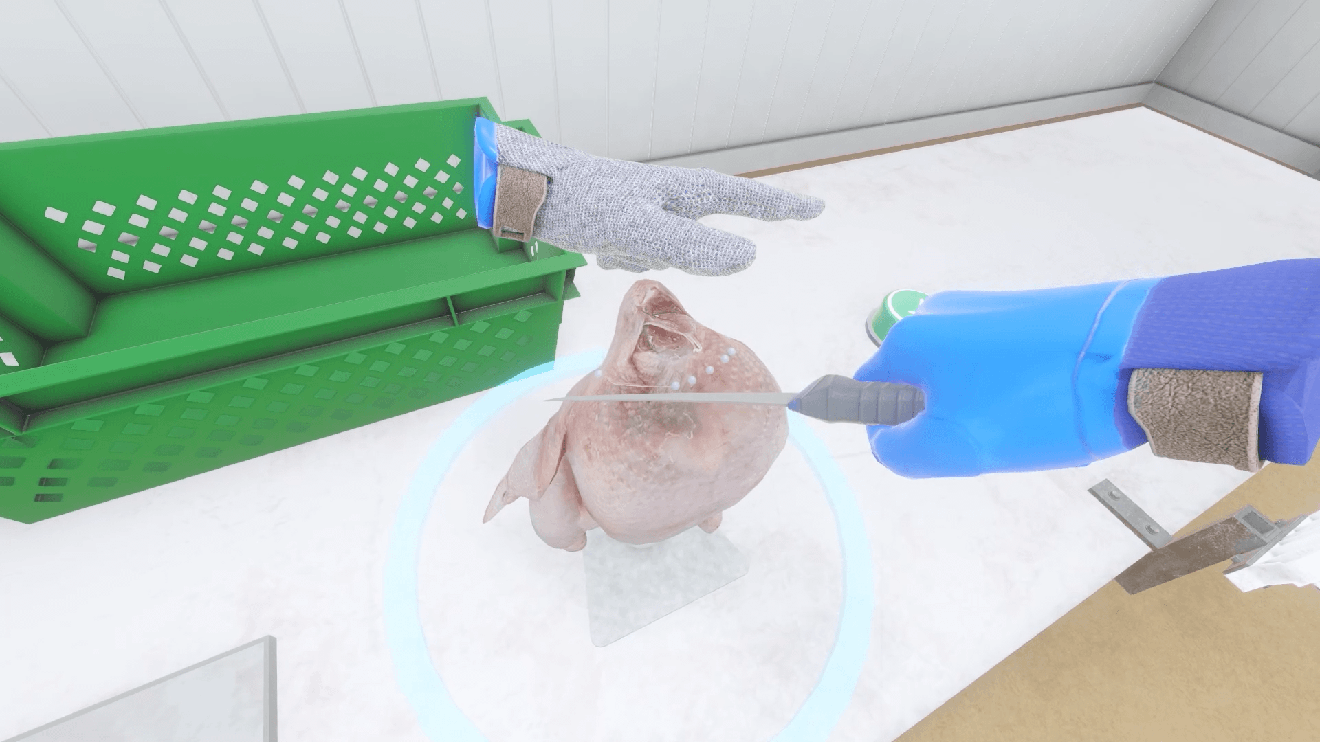
4.3. Poultry cutting
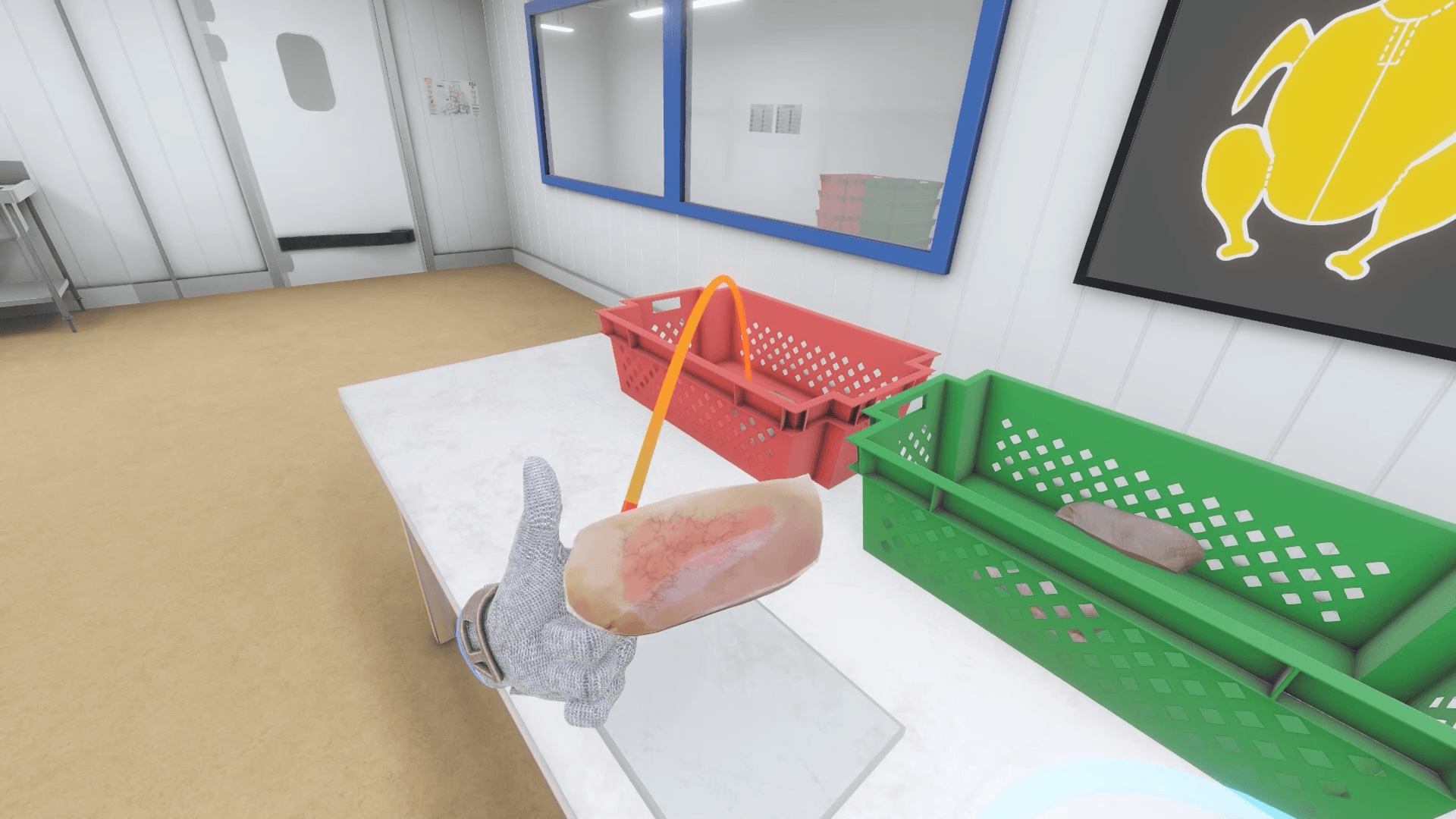
The user starts the scenario in a slaughterhouse, with a chicken carcass on a shell and a knife in hand. Their mission is to cut up the chicken according to the correct procedure displayed on a screen in front of him.
4.3.1. Exercise Plan
To complete the exercise, they must perform the actions in the following order:
-
Cutting the neck
-
Grab the neck and place it in the red sorting bin
-
Cutting the first wing
-
Grab and place the first wing on the cutting board
-
Cutting the second wing
-
Grab and place the second wing on the cutting board
-
On the cutting board, cut the first wing into 3 parts
-
Place the previously cut parts one by one in the sorting bins
-
On the cutting board, cut the second wing into 3 parts
-
Place one by one the previously cut parts in the sorting bins
-
Cut out the first leg
-
Grab and place the thigh in one of the sorting bins
-
Cut out the second thigh
-
Grab and place the thigh in one of the sorting bins
-
Cut the first fillet
-
Grab and place the fillet in one of the sorting bins
-
Cut the second fillet
-
Grab and place the net in one of the sorting bins
-
Cut off the top of the cartilage
-
Grab and place the top of the cartilage in one of the sorting bins
4.3.2. Scenario flow
The user starts the scenario with the following briefing:
Cutting a chicken
Cut the chicken according to the diagram on the screen in front of you, passing the knife over the dotted lines. Check the quality of each piece and place them in the appropriate bins.
|
Tip
|
Keep your knife sharp with the knife sharpener on the right side of your workstation. |
The user stands in front of the chicken and proceeds to cut the neck of the chicken.
With their blade, they must follow the cutting line marked with small dots.
|
Important
|
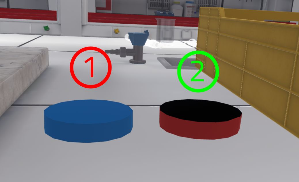
For a piece to be considered fully cut, all the cutting points must have been touched by the blade. To better visualize the cut, the user can rotate the entire chicken by grasping the blue ring hologram and rotating it to the right or left. |
Once the neck is cut, the user will need to grab the part. A red arc will appear indicating that the part should be placed in the red bin.
NOTE:
-
For each piece cut, the user must check the quality of the piece.
-
Two bins are available to the user to sort the pieces of meat he has cut: a red bin and a green bin.
-
The red bin represents the rejects and the green bin the valid pieces.
-
If a piece has defects (e.g. hematoma), it will go into the red bin.
-
A red arc will appear as a visual indicator to help the user to sort.
The user can move on to the next piece: the wing.
They cut and place the first wing on the cutting board and then the second. Each wing needs to be recut in 3 parts. They can then proceed to the sorting procedure on each part of the cut wing.
|
Important
|
As the user uses the knife, the blade will become dull. In order to continue with the cutting procedure the user must regularly run the knife through the sharpener to sharpen it or risk penalties on the final score. |
The user then proceeds to cut and sort the first leg. This operation must be repeated for the second leg as well.
Once the legs have been sorted, the user cuts and sorts the first fillet. This operation must be repeated for the second fillet as well.
Finally, the user cuts and sorts the upper cartilage.
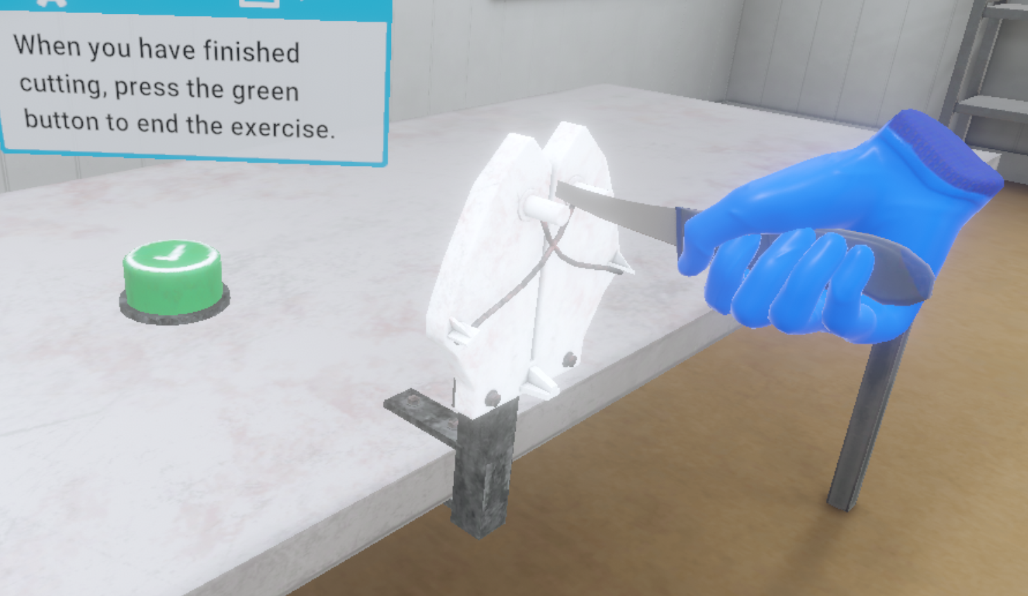
When the user believes that they have finished their cutting work, they press the validation button which will end the countdown. The user will then be teleported back to the lobby in front of the scoring screen.
4.3.3. Criteria for evaluating the exercise
![]() Average Time per Piece: Evaluates the time taken to cut each piece.
Average Time per Piece: Evaluates the time taken to cut each piece.
![]() Adherence to Procedure: Evaluates the adherence to the ideal cutting procedure.
Adherence to Procedure: Evaluates the adherence to the ideal cutting procedure.
![]() Knife Upkeep: Checks if the user has used a blade that is too blunt to cut parts.
Knife Upkeep: Checks if the user has used a blade that is too blunt to cut parts.
![]() Quality Control: Evaluates the user’s sorting according to the quality of the meat.
Quality Control: Evaluates the user’s sorting according to the quality of the meat.
4.4. Chemistry
The user will perform an experiment in a chemistry laboratory. While following a procedure, they will weigh, mix and heat products to observe a chemical reaction.
4.4.1. Exercise Plan
To complete the whole exercise, the user will have to follow the following instructions:
-
You must weigh 180 mg of 4-hydrazino benzenesulfonic acid, with a tolerance of 5%. To begin, turn on the scale by pressing the first button.
-
Take a clean, empty container suitable for the chemical and place it on the scale pan. Press the second button to tare.
-
Remove the container from the scale pan.
-
Take a clean spatula and transfer 180mg of the product into the container. Weigh the filled container. If you are satisfied, confirm by clicking on the 3rd button.
-
Using the reflux heater with magnetic stirrer, you will mix and heat different products in order to merge them. To continue, open the fume cupboard to half height.
-
Place the funnel on the left opening of the triple-neck flask.
-
Transfer the powders into the triple-neck flask using spatulas and the funnel.
-
Open the vial containing 0.56 ml of H2SO4 and transfer its contents into the triple-neck flask using the funnel.
-
Close the vial. Remove the funnel.
-
Place the cap of the triple-neck flask on the left side of the triple-neck flask.
-
Adjust the height of the elevator so that the agitator reaches the triple-neck flask.
-
Position the reflux column over the center hole of the triple-neck flask.
-
Position the thermometer on the right-hand port of the triple-neck flask.
-
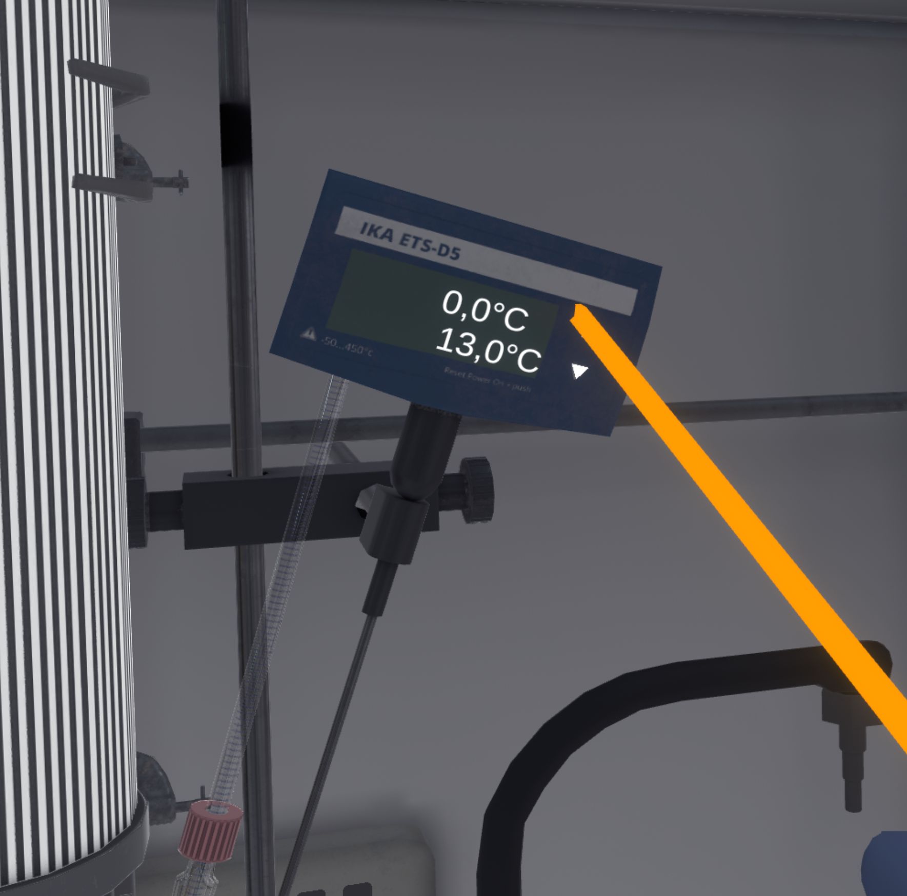
Set the expected temperature on the blue probe to 65°C. The longer you hold down the arrows, the faster the speed increases.
-
Set the stirrer between 350 and 500 rpm.
-
Set the heating temperature on the stirrer to 60°C.
-
If you have followed the instructions correctly, you can observe a chemical reaction! To complete the exercise, check the temperature of the solution by clicking on the icon near the thermometer.
-
You will be teleported to the lobby.
4.4.2. Scenario sequence
The exercise is divided into two parts: one consists of weighing powder on a scale. The other part consists in mixing and heating different products in a triple-neck flask in order to merge them with the help of a reflux heater with a magnetic stirrer.
To begin, the user will approach the scales, and turn on the single scale.
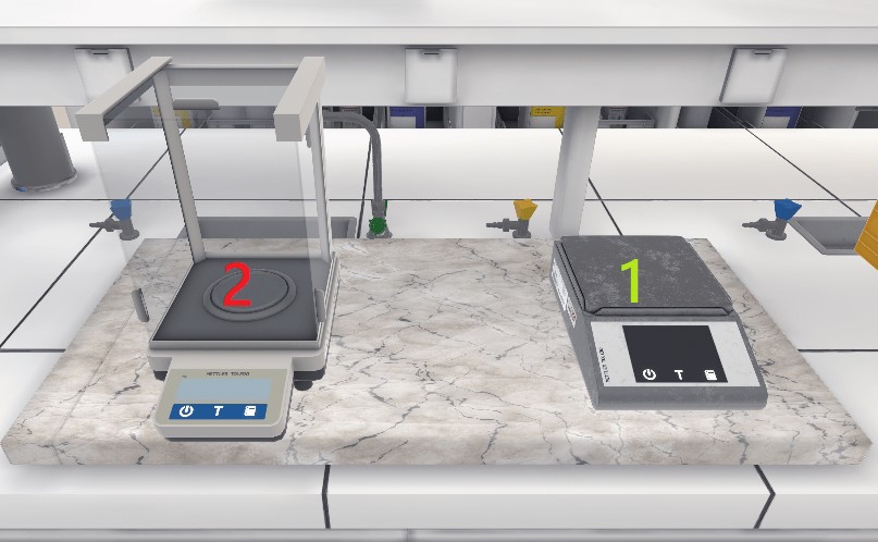
-
Simple scale: To be used
-
Analytical scale: Do not use: it is too precise for this manipulation
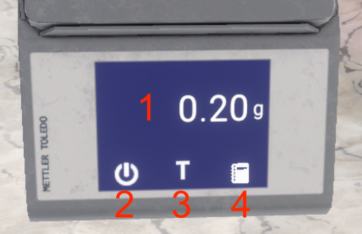
-
Display of the weight measured by the scale, in grams (1g = 1000mg)
-
Button to turn on/off the scale
-
Button to perform the tare of the scale
-
Button to confirm the weighed result and continue the exercise
Then, they will place an empty and clean jar on the scale and perform the tare. Then, they will retrieve the jar and place it on the work surface.
The user must transfer 180 mg of 4-hydrazino benzenesulfonic acid into the jar he has just tared. When opening the bottle, the user must be careful to place the cap the right way up on the work surface.

-
Incorrect: An error will be triggered
-
Correct
They must use the spatulas to perform this decanting.
|
Note
|
The user will be able to transfer powder with the spatulas. The user must dip the spatula into the bottle (or jar) containing the powder, until a colored gauge appears. This gauge indicates the amount of powder in the spatula. The spatula fills gradually. If the user tips the spatula over a second container, the powder will fall out. The user then transfers the product from the spatula to the container. 
Figure 83. Using a spatula: filling

Figure 84. Using a spatula: emptying
Figure 85. Both types of spatulas
|
The user must not put the product back into its original container. If they have taken too much product, they must put the powder in the waste beaker

The user should transfer product into the jar outside the scale, otherwise they may drop powder on the scale pan, which will distort the weight. At this point, they must take the brush to clean it.

When the user is sure of the quantity of product weighed, they will confirm by pressing the 3rd button.
The second part of the exercise begins. They will have to approach the fume hood and open it halfway.
|
Note
|
To open a fume hood, the user has to grab the glass of the fume hood and make a movement from the bottom to the top, then let go of the glass so that it opens. The user can open it halfway or all the way. If the fume hood is fully open, there is a greater safety risk. If the fume hood is left open too long, an audible alarm will sound. The user must close the fume hood to stop it. 
Figure 88. Fume hood closed

Figure 89. Fume hood half open

Figure 90. Fume hood open
The user can also turn on the fume hood light by pressing the green button on the control panel. 
Figure 91. Turn on the fume hood light
|
Next, place the funnel on the left side of the triple-neck flask.
They must transfer all the powders (including the one that has just been weighed) into the triple-neck flask with the help of spatulas, above the funnel: 180 mg of 4-hydrazino benzene sulfonic acid and 218 mg of 2,2,3,3-tetrahydroxysuccinic acid*.

-
Jar containing 180mg of 4-hydrazino benzenesulfonic acid.
-
Jar containing 218mg of 2,2,3,3-tetrahydroxysuccinic acid .
-
Flask containing 0.56 ml of H2SO4 .
Then, they should transfer 0.56 ml of H2SO4 into the triple-neck flask (still above the funnel), and then close the bottle of H2SO4.
|
Note
|
To transfer liquid from one container to another: He should grab the first container and tip it over until liquid flows out, and aim for the neck of the second container. 
Figure 93. Example of liquid transfer by flow
As long as a second container is not targeted, the first container will not have its contents change. |
When the triple-neck flask is filled, the user can remove the funnel and replace it with the triple-neck flask cap.
The user must interact with the lab elevator to adjust the height of the stirrer until the heat-on touches the triple-neck flask.
The user will continue with the set-up: the reflux column should be positioned on the center hole of the triple-neck flask and the thermometer on the right hole of the triple-neck flask.

The user will set up the reaction, setting the control temperature on the blue probe to 65 °C by clicking on the arrows. The longer they presses, the faster the temperature changes.
On the magnetic stirrer, it is necessary to set the speed of rotation between 350 and 500 rpm and the heating temperature to 60 °C. To do this, they must press the interaction button near the wheels and rotate his wrist to change the values.

The user can observe misting on the walls of the triple-neck flask and see that the solution has changed color if they have followed the instructions correctly.
To complete the exercise, the user must check the temperature of the solution by clicking on the icon near the thermometer. The user will then be teleported back to the lobby in front of the scoring screen.
4.4.3. Evaluation criteria for the exercise
![]() Execution time: Evaluates the speed of the user in completing the requested tasks.
Execution time: Evaluates the speed of the user in completing the requested tasks.
![]() Weighing: Evaluates the result and the correct sequence of actions during the first part of the exercise.
Weighing: Evaluates the result and the correct sequence of actions during the first part of the exercise.
![]() Mixing and heating : Evaluates the result and the good sequence of actions during the second part of the exercise.
Mixing and heating : Evaluates the result and the good sequence of actions during the second part of the exercise.
4.5. Logistics
Working in a logistics warehouse, the user will have to perform package receiving, package retrieval and order picking.
4.5.1. Exercise Plan
To complete the exercise, the user must carry out the actions in the following order:
-
You are a versatile logistics agent. During this session, you will perform a receiving, a picking and a shipping task.
-
Confirmation of start-up instructions.
-
Retrieve the laser pointer from the table.
-
Fitting Personal Protective Equipment (PPE).
-
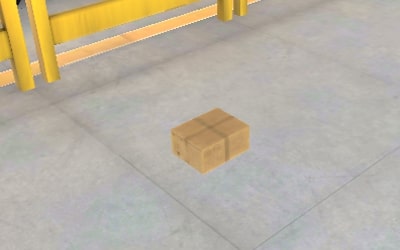
Go to receiving dock to pick up package.
-
Transport the package to the administrative receiving area.
-
Open package with the box cutter on preparation table.
-
Scan the delivery note inside the package.
-
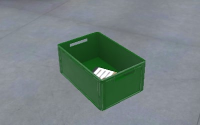
Place products in conveyer box.
-
Send the conveyer box onto the conveyor belt.
-
Move to small-volume storage area.
-
Collect products at end of conveyor belt.
-
Place products in appropriate storage areas.
-
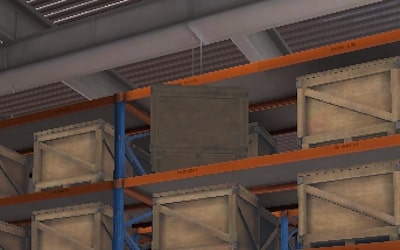
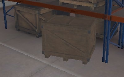
In Zone 2, take the scanner and go to the wooden crate at the appropriate location.
-
Scan the label on the wooden crate
-
Pull out the wooden crate with the pallet truck
-
Open wooden crate
-
Take the product contained in the wooden crate, and proceed to the preparation area in Zone 3.
-
Prepare the order by placing the products indicated on the screen in the preparation bin.
-
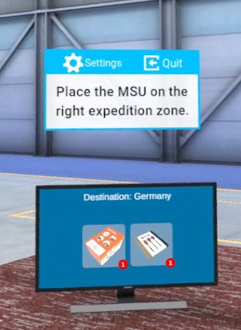
Place the preparation bin on the Mobile Storage Unit (MSU).
-
Place the MSU on the appropriate shipping dock .
-
Release the shipment in the administrative shipping area.
4.5.2. Scenario Sequence
Warehouse floor plan
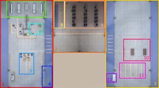
-
1 - Zone 1
-
2 - Zone 2
-
3 - Zone 3
-
4 - Protected area
-
5 - Receiving dock
-
6 - Administrative receiving area
-
7 - Small and medium-volume storage area
-
8 - Large-volume administrative receiving area
-
9 - Large-volume storage area
-
10 - Order picking area
-
11 - Shipping dock
-
12 - Administrative shipping area
The scenario is divided into 2 parts.
Receiving a Package (1/2)
This part involves receiving a package, from receiving to storage, including administrative receiving.
After confirming the instructions, the user must collect their protective equipment and a laser pointer.
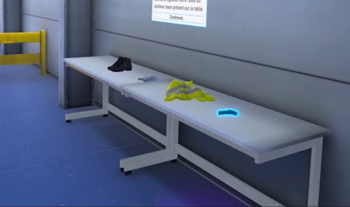
To put on PPE, place one hand on the objects and press the "Action" button. The laser pointer must be grasped using the grasp button. If the laser pointer is dropped, it is automatically stored on the user’s belt and will follow the user’s movements.
The user can then leave the starting area and head for the receiving dock.
Once at the receiving dock, the user must retrieve the highlighted package and take it to the administrative receiving area.
On the desks in the administrative reception area, grasp the cutter and apply it to the opening to open the package.
Once the package has been opened, the user can retrieve the receipt and scan it with the scanner placed on the desk.
Following the success sound, the products in the package can be transferred to the conveyer box, and the box deposited on the conveyor belt.
|
Note
|
The empty box can be placed in the yellow garbage can. |
The user can then proceed to the small-volume storage area to retrieve the conveyer box at the end of the conveyor belt.
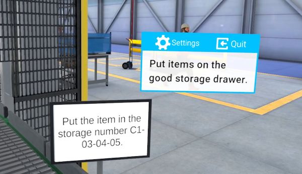
The user can then take the products from the conveyer box and place them in the storage drawer indicated on the screen at the end of the conveyor belt. The requested location is random. Once the products have been put away, the "receiving" part of the exercise is complete.
|
Note
|
The conveyer box can be placed on the stack of conveyer boxes next to the end of the conveyor belt. |
Order picking (2/2)
This part consists of preparing an order, starting with the collection of a product from the warehouse, the preparation of the package and its deposit on the shipping dock.
This phase follows directly on from the first order reception phase. To start this part, the user must move to the high-volume administrative reception area located in Zone 2.
When they arrive in this area, they take the scanner and proceed to the wooden crate whose location is indicated on the monitor.
After scanning the label on the appropriate crate, the user will pull the wooden crate using the pallet truck located to the right of the high-volume administrative reception area. It is possible for the user to move the crate by hand, but this would be a mistake given its weight.
Once the crate has been pulled out, the user can open the crate and take the product inside.
For the next steps, the user must transport the item to the order picking area.
The first step is to assemble the order with the products shown on the screen.
Once the order has been assembled in the picking bin, place the bin in the Mobile Storage Unit (MSU). Then grab a handle of the MSU and, holding down the grab button, teleport to the order’s destination zone. The MSU will gradually move towards the user as long as the button is not released.
|
Note
|
You can see the order destination on the monitor located on the picking table. |
When the MSU has been routed to a shipping zone, the user can end the exercise by clicking on the button on the monitor in the administrative shipping zone.
4.5.3. Exercise evaluation criteria
![]() Execution quality: Evaluates the user’s ability to follow the steps correctly.
Execution quality: Evaluates the user’s ability to follow the steps correctly.
![]() Execution time: Evaluates the user’s speed in completing tasks.
Execution time: Evaluates the user’s speed in completing tasks.
![]() Safety: Evaluates the user’s ability to perform safety actions such as putting on protective equipment or not pulling a heavy crate.
Safety: Evaluates the user’s ability to perform safety actions such as putting on protective equipment or not pulling a heavy crate.
4.5.4. Hazard verification
At the start of the exercise, three hazards are randomly generated in the warehouse. The user can use the laser pointer attached to his belt at the start of the exercise to point them out, although missing them has no impact on the overall score.
The list of hazards that can be found is as follows:

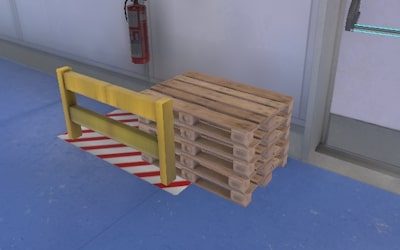
4.6. Carpentry
This module offers the user the opportunity to make two cuts of a board using a band saw.
|
Note
|
The user will be assessed on their ability to follow the cutting lines while adhering to safety measures and optimizing the use of materials. |
4.6.1. Exercise Plan
To successfully complete the exercise, the user must perform the following steps in the correct order:
-
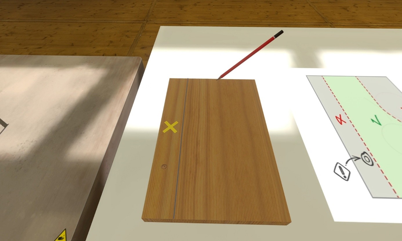
Mark the first cutting line on the board using a pencil
-
Place the board on the workbench
-
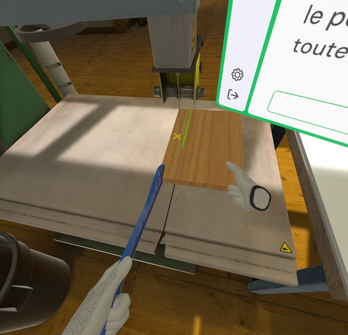
Manually cut as much of the board as safely possible
-
Use the push stick to complete the cut
-
Recycle the wood scrap
-
Mark the second cutting line on the board using a pencil
-
Place the board on the workbench
-
Manually cut as much of the board as safely possible
-
Use the push stick to complete the cut
-
Recycle the wood scrap
-
Place the board back on the workbench
4.6.2. Scenario Flow
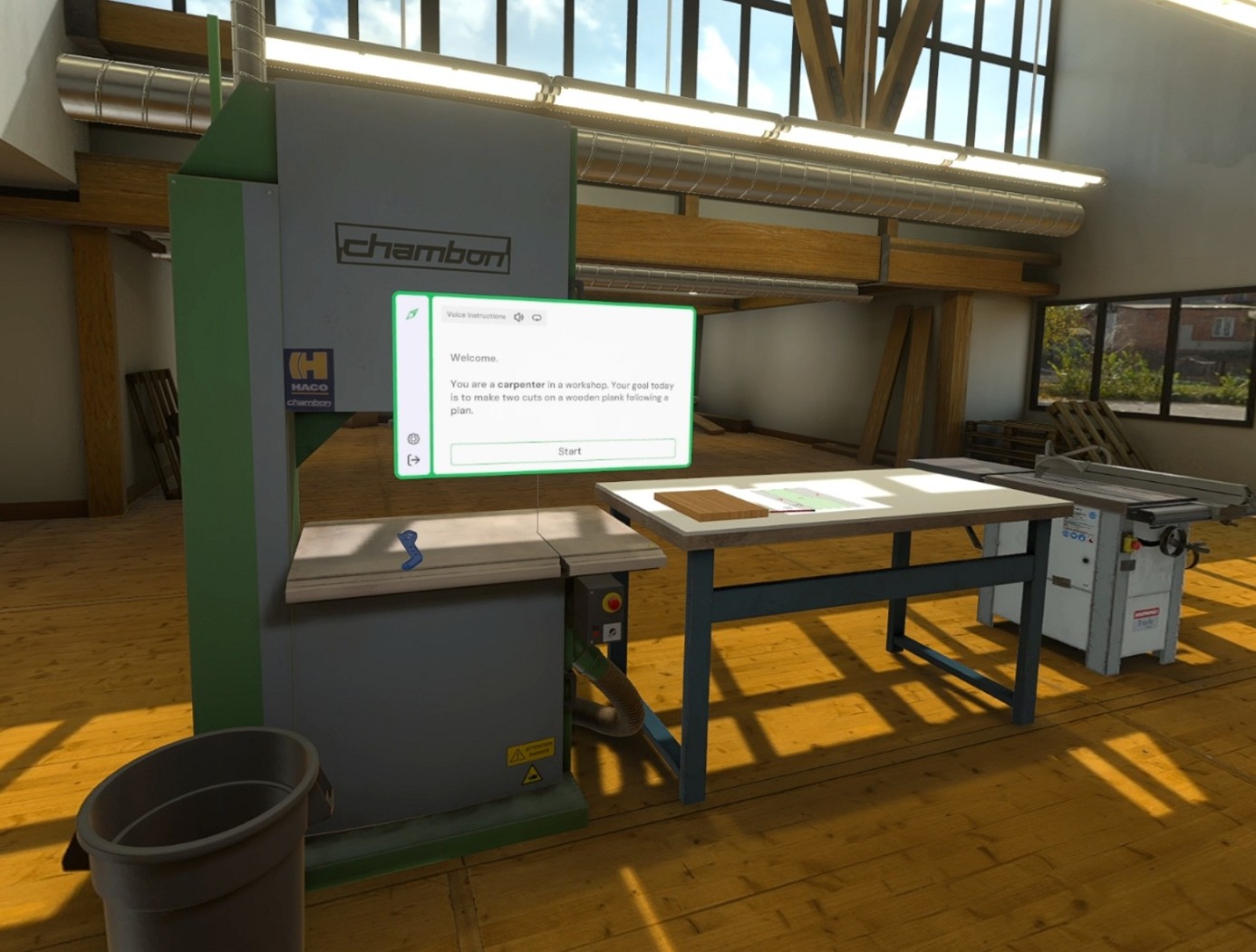
The user starts the scenario with the following briefing:
Welcome.
You are a carpenter in a workshop. Your goal today is to make two cuts on a wooden board following a plan.
|
Important
|
While cutting, the user must always keep one hand in contact with the board, otherwise their safety score will be affected. Similarly, it is important to use the pusher when the hand enters the safety zone. Every second spent in the safety and danger zone will impact the safety score. |
|
Important
|
If the cut deviates too far from the plan, the piece will be considered defective, and a new board will automatically appear. This will impact the material optimization score. |
The user positions themselves in front of the workbench and examines the cutting plan. Using a pencil, they draw thr first line.
Following the first line, the user must place the board in front of the band saw and hold the board with both hands to proceed with the cut along the line.
They can then use the pusher when their hand nears the warning zone.
Once the first cut is made, the user must recycle the scrap by placing it in the bin located to the left of the band saw. They place the remaining section of board on the workbench in order to draw the second cutting line using the pencil.
|
Note
|
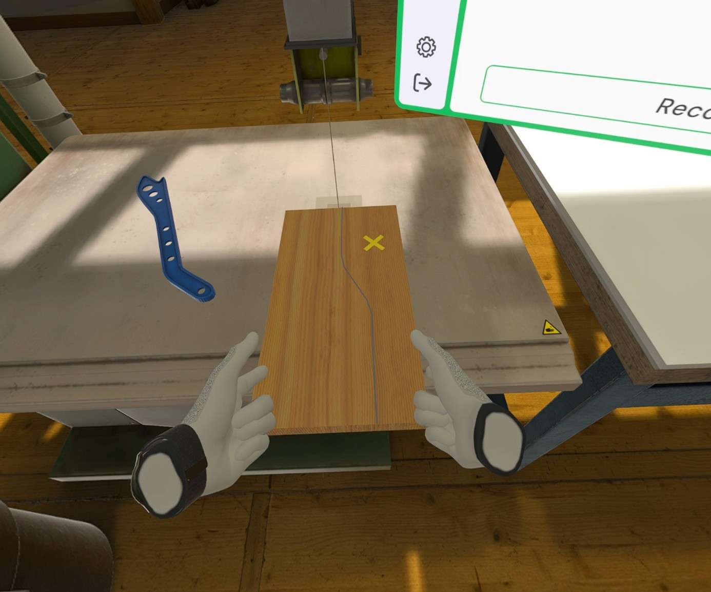
The accuracy of the cut is indicated by the color of the line�: |
-
Green: the cut is precise
-
Yellow: the cut is drifting from the guideline
-
Red: the cut is too far from the guideline
Once the second cut is made, the user must recycle the scrap by placing it in the bin located to the left of the band saw. They place the finished board on the workbench.
Once the steps are completed, the user will be teleported to the lobby in front of the scoring screen.
4.6.3. Exercise Evaluation Criteria
![]() Precision: Assesses whether the cut follows the plan.
Precision: Assesses whether the cut follows the plan.
![]() Safety: Validates the safety conditions of the operations.
Safety: Validates the safety conditions of the operations.
![]() Material Optimization: Evaluates the number of boards used.
Material Optimization: Evaluates the number of boards used.
5. Service Module
5.1. Cleaning
Working in a school environment, the user will be asked to clean three areas: the tiled floor of a corridor, the wooden platform in the classroom and the linoleum floor of a classroom.
The cleaning module will require the user to be meticulous and choose the right products to apply to the surfaces.
5.1.1. Exercise Plan
To complete the whole exercise, the user will have to perform the actions in the following order:
-
Confirm the instructions at startup
-
Clean the floor with the floor sweeper machine
-
Move to the door and open it
-
Grab the water canister and pour the water into the bucket
-
Grab the microfiber broom (blue in color) and dip it into the bucket
-
Sweep the microfiber broom over the entire ink stain
-
Grab the soap cleaner and pour the liquid into the bucket
-
Grab the mop (green in color) and dip it into the bucket
-
Mop the entire stain on the linoleum floor
5.1.2. Scenario flow
The user starts the scenario with the following briefing:
Cleaning
You are a maintenance worker in a secondary school. Your task is to clean the floor of classroom A24 and the adjoining corridor.
Tip: Choose the products you are going to use carefully.
At the start the user is in a corridor where they are asked to clean the task with the brush.
The user grabs the handle of the machine left near the area and cleans the floor.
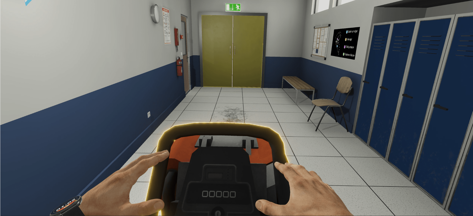
Once the action is complete, they will have to go to the classroom. To get there, they will have to interact with the door handle.
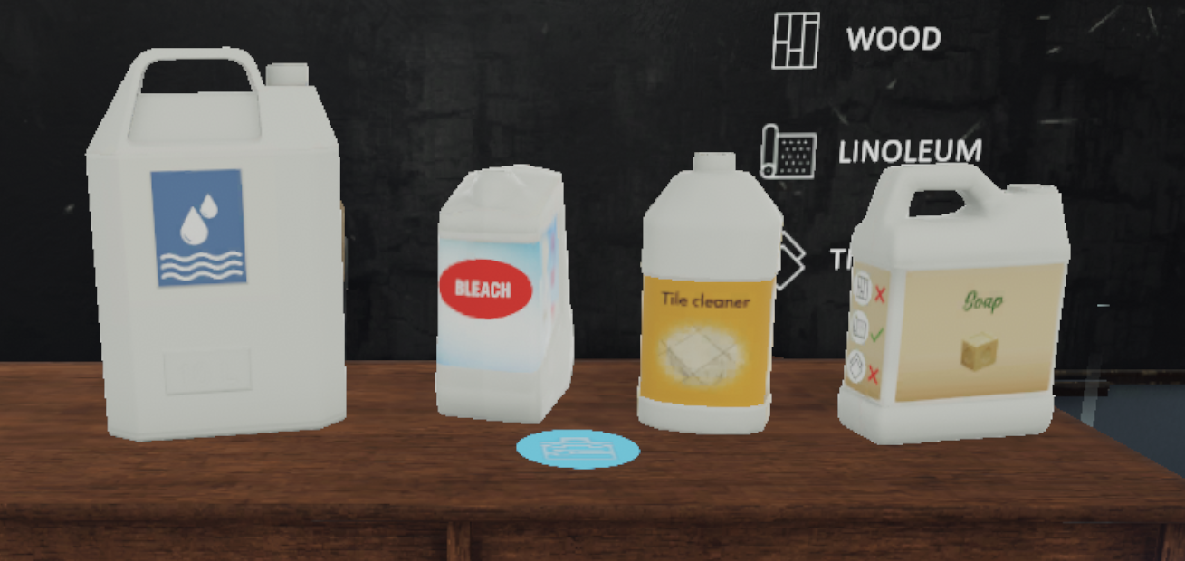
Two tasks are visible in the classroom. All the necessary products and buckets will be provided as well as all the maintenance materials.
The user is first asked to treat the stain on the platform with the microfiber mop.
The user should consult the pictograms on the cleaning products to check the compatibility of each with the surface to be treated. As the platform is made of wood, the user must choose the water canister, the only product compatible with the floor.
While holding the canister, the user pours the contents of the water canister into the bucket.

The user then grabs the microfiber mop (in blue) and wets it by dipping it into the bucket.

The user will then be able to clean the stain by sweeping the area while gripping the broom handle.
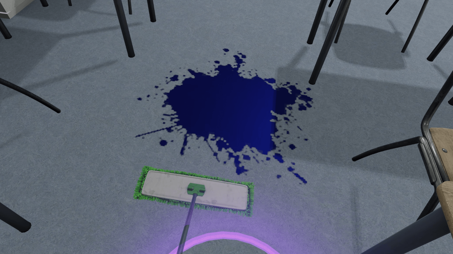
Once the stain on the stage has been cleaned, the user will be asked to clean the blue ink stain.
The user repeats the previous operations, but this time choosing the soap cleaner as the cleaning product compatible with the linoleum floor and the mop (in green).
Once the mission is completed, the user is teleported back to the lobby in front of the scoring screen.
5.1.3. Criteria for evaluating the exercise
![]() Execution Quality: Checks that the user has cleaned up each task using an effective, non-corrosive product.
Execution Quality: Checks that the user has cleaned up each task using an effective, non-corrosive product.
![]() Execution Time: Assesses how quickly the user completes the requested tasks.
Execution Time: Assesses how quickly the user completes the requested tasks.
5.2. Car Mechanics
The car mechanics module will propose to perform two basic maintenance tasks on a vehicle: change the oil and change a tire
The user will be guided through these two tasks, but the instructions will leave room for interpretation in order to check their ability to read the indications on the devices, use the right tools and have the right environmental protection practices.
|
Note
|
As the performance of a car mechanic is also linked to time, the exercise will be timed and will have to be completed within 5 minutes to get the maximum mark, each second lost after this limit will result in the loss of points in the final evaluation. |
5.2.1. Exercise Plan
To complete the whole exercise, the user will have to perform the actions in the following order:
-
Confirm the instructions at start-up
-
Raise the hydraulic lift
-
Place the drain pan under the car
-
Grab the wrench
-
Unscrew the drain plug with the wrench
-
Screw the drain plug back in
-
Empty the drain pan into the blue container
-
Lower the hydraulic lift
-
Open the hood
-
Remove the engine oil tank cap
-
Take the oil can and fill the tank
-
Close the engine oil tank cap
-
Close the hood
-
Raise the hydraulic lift to access the wheels
-
Grab the impact driver
-
Loosen the 5 bolts on the right front wheel
-
Activate the tire changer to remove the tire from the rim
-
Grab the used tire and place it on the used tire recycling area
-
Grab a tire with the part number P295 / 45ZR18 from the tire rack
-
Place the new tire on the rim
-
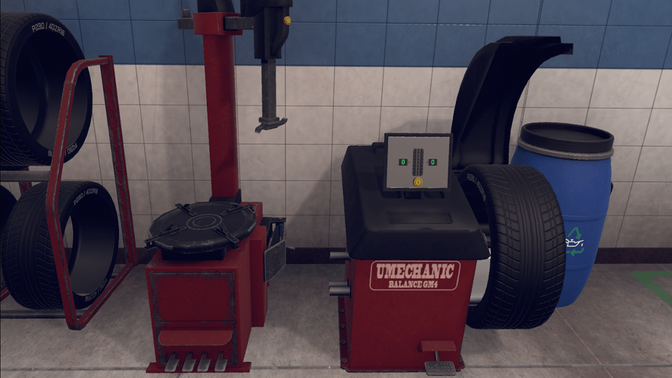
Pick up the complete wheel and place it on the balancer
-
Operate the balancing machine
-
If the balancer indicates 0 - 10 grab a 10 lead on the servo and place it on the wheel rim.
-
Grab the wheel and place it on the car in its location.
-
Grab the impact driver and screw the bolts back on.
5.2.2. Scenario flow
The user starts the scenario with the following briefing:
Motor vehicle mechanics
As a mechanic, you need to perform some maintenance tasks on a vehicle. The required tasks are listed on the screens.
Tip: When working, use the correct tools and adhere to environmental regulations.
When starting, the user is presented with a car mounted on a hydraulic lift in a garage environment. Their first task is to change the oil in this car.
To do this, the user raises the hydraulic lift using the control panel in order to access the drain plug located under the car’s engine.

Before loosening the plug, they grabs the drain pan and place it on the ground under the plug. They take the wrench on the trolley and loosen the plug by placing the wrench over the drain plug and pressing the trigger.
If the user has placed the drain pan correctly, the used oil will pour into the pan.
The user must then dispose of the oil in the waste oil container (blue).
The user closes the drain plug and positions the hydraulic lift on the ground in order to open the front hood of the car.
Under the hood is the engine oil tank. Using the oil can on the trolley, the user removes the cap and pours the contents of the can into the tank.

Finally, they put the cap back on and closes the hood.
The user’s second task is to replace the car’s worn-out tire.
In this scenario, the user will only work on the right front wheel (passenger side).
First, thee position the lift so that they can access the wheels.
They take the impact driver from the tool stand and loosen the 5 bolts on the right front wheel.
Once the bolts are loosened, they pick up the wheel and place it on the tire changer tray behind them. They operate the tire changer to remove the tire.
They should then pick up and place the used tire in the used tire recycling area.
They pick up one of the tires (carefully selected) from the tire rack and place it on the rim of the previously removed wheel.
|
Note
|
The user should check the part number of the used tire to select the new tire. |
Now that the wheel mounting is complete, the user can proceed to the wheel balancing step. The user picks up the wheel, places it on the balancing machine and activates it.
To ensure that the weight of the wheel is distributed evenly, the balancing machine must indicate 0 - 0. If the result of the balancing machine is not correct, the user must install counterweights.
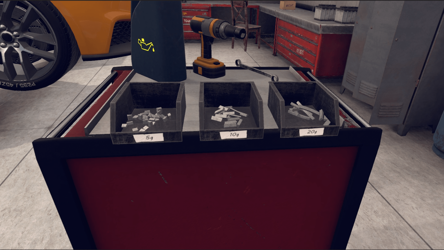
For example: the balancer indicates 0 - 10 as a value (the leftmost number corresponds to the left side of the wheel and the rightmost number to the right side of the wheel).
The user should therefore place a 10 on the right side of the wheel. The user will then operate the balancer again until the values show 0 - 0.
The wheel is finally balanced, the user can then grab the wheel and place it on the car in its intended location. Finally, they take the impact screwdriver again and reattaches the 5 bolts.
Once the steps have been completed, the user will be teleported to the lobby in front of the scoring screen.
5.2.3. Criteria for evaluating the exercise
![]() Respect for the Environment: Evaluates if the user has integrated environmental protection measures into their performance.
Respect for the Environment: Evaluates if the user has integrated environmental protection measures into their performance.
![]() Execution Quality: Evaluates the execution of tasks requested of the user.
Execution Quality: Evaluates the execution of tasks requested of the user.
![]() Execution Time: Evaluates the speed of the user in completing the requested tasks.
Execution Time: Evaluates the speed of the user in completing the requested tasks.
5.3. Personal Care
In this exercise, the user will have to respond to the services and care at home of an elderly person who has lost their autonomy. They will be required to provide assistance with housework, meal preparation and interpersonal skills.
5.3.1. Exercise Plan
The user can complete the tasks in any order they wish, but it is best to follow the order below in order to meet the ideal schedule.
Here is an example of a timeline of actions that would complete the whole exercise.
-
Confirm the instructions at start-up
-
Go and see Rose
-
Ask her how she is
-
Accept her request
-
Go to the kitchen
-
10:00: Grab broom and pick up glass debris
-
Consult the notepad on the kitchen island.
-
10:30: Open the fridge.
-
Grab the soup pot and place it on the cooker
-
Wait for the soup to heat up (steam comes out of the pot)
-
11:30: Grab the pot and place it on the table in the dining room
-
Grab the plate and place it on the table in the dining room
-
12:00: Ask Rose to come to the table
-
1:00 pm: Talk with Rose for an hour
-
Talk to Rose again and help her back to the sofa
-
2:00: Take the mail (newspaper) and put it on the kitchen island
-
2.30 pm: Make the bed in the bedroom
-
3.00pm: Talk to Rose and ask her if she needs anything
-
Give her the book
-
4 pm: Tell Rose you are leaving

5.3.2. Scenario flow
|
Important
|
This scenario flow refers to the exercise plan mentioned in the previous chapter. The user can complete the tasks in any order they wish, but the flow below is an example of a timeline that would allow the user to complete the whole exercise on time. |
The user starts the scenario with the following briefing:
Personal Care
You have to help Rose, a person who has lost her independence, with her daily tasks. Your daily schedule is on the kitchen table
Tip: You can explore the house at will; only when an action is started will the timing begin.
Once the briefing is accepted, the user starts in the entrance of the house. The elderly person’s avatar is on the sofa in the living room. A to-do list is prominently displayed on the kitchen counter.
On arrival, the user can go and greet Rose, who will inform the user that she has broken a glass and ask her to pick up the debris.
The user then goes to the kitchen, grabs the broom, and sweeps up the debris.
They consult the schedule to find out what their tasks are.
If Rose has to eat before 12:30, it is best for the user to prepare the meal first.

To do this, they opens the bottom compartment of the fridge and grab the pot of soup.
They put the pot on the cooker and heat the soup.
Once the soup is warm (steam comes out of the pot indicating it is ready), they pick up the pot and the plate on the island and bring them to the dining room table.
The user will need to speak to Rose to indicate that the meal is ready.
During the meal, the user can then chat with her.
Once the conversation is over, the user should consult with Rose to help her back to the sofa.

The user can then pick up the mail. They pick up the newspaper at the bottom of the front door and put it on the kitchen island.
They talk to Rose again and ask her if she needs anything. Rose then asks them to bring her the book.
They grab the book from the coffee table in front of her and give it to her.
Finally they have to go to the bedroom and make the bed.
It is now 4pm, the user has finished their day. They should inform Rose that he is leaving.
Once the steps are completed, the user will be teleported back to the lobby in front of the scoring screen.
5.3.3. Criteria for evaluating the exercise
![]() Communication: Evaluates the user’s ability to communicate with the avatar.
Communication: Evaluates the user’s ability to communicate with the avatar.
![]() Tasks Completed: Evaluates that all tasks have been completed.
Tasks Completed: Evaluates that all tasks have been completed.
![]() Time Management: Validates that the tasks have been done in an optimal order.
Time Management: Validates that the tasks have been done in an optimal order.
5.4. Fiber Optics
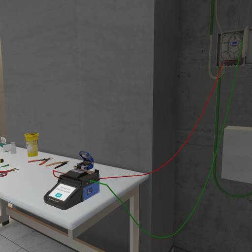
The objective of this exercise is to step into the role of a fiber-optic technician and learn the proper procedure and best practices for connecting an apartment to the fiber network.
5.4.1. Exercise Plan
To complete the exercise successfully, the user must perform the following actions in order:
-
Take the splice protector from the table and slide it onto one of the fibers to be fused. It will protect the fibers after fusion.
-
Select the first fiber to strip. Use the appropriate 900-micron fiber strippers to remove the mechanical coating from the end of the fiber over a length of approximately 7 cm. Remember to dispose of all waste in the yellow bin.
-
Using the 250-micron fiber strippers, remove the fiber’s coating over a length of 25–35 mm.
-
Moisten a lint-free wipe with isopropyl alcohol and carefully clean the fiber strand.
-
Place the fiber strand into a clamp.
-
Insert the clamp into the fiber cleaver and use it to make a perfectly straight cut on the fiber.
-
Place the fiber strand into the fusion splicer.
-
Select the second fiber to strip. Use the 900-micron fiber strippers to remove the mechanical coating from the end of the fiber over a length of approximately 7 cm.
-
Using the 250-micron fiber strippers, remove the fiber’s coating over a length of 25–35 mm.
-
Moisten a lint-free wipe with isopropyl alcohol and carefully clean the fiber strand.
-
Place the fiber strand into a clamp.
-
Insert the clamp into the fiber cleaver and use it to make a perfectly straight cut on the fiber.
-
Place the fiber strand into the fusion splicer.
-
Press the OK button to start the fiber fusion process.
-
Remove the fiber from the fusion splicer and slide the splice protector over the joint.
-
Place the fiber into the fusion splicer’s oven.
-
Place the fiber inside the building distribution box.
-
Now verify that your connection is correct. First, disconnect the A1 cable at the building distribution box and plug in the fiber test pen.
-
Go to apartment A1 to confirm that the fiber connection is active up to the ONT (Optical Network Terminal).
-
Disconnect the test pen and reconnect the A1 cable to the building distribution box.
-
Exit the building to complete the exercise and return to the main lobby.
5.4.2. Scenario Overview
Briefing
The user begins the scenario with the following briefing:
Welcome.
You are a fiber technician for an Internet Service Provider (ISP). Your goal today is to finish connecting an apartment properly splicing two fibers together.
You can leave the exercise at any time by going to the entrance of the building.
The briefing is automatically confirmed when the user begins interacting with the objects.
Installing the Splice Protector
The user must pick up the splice sleeve and place it onto one of the fibers (green or red). The sleeve automatically snaps into position magnetically when released near the correct area.

If this step is skipped, it will affect the Quality of Workmanship score.
Stripping the 900-micron Jacket from One of the Two Fibers
To continue, the user must choose a fiber to strip (green or red). They will use the 900 µm stripping tool to remove the mechanical jacket from the end of the fiber over a length of approximately 7 cm.
The user must grab the stripper, move it to the indicated area on the fiber (between 5 cm and 9 cm, visually highlighted in yellow), and press the Action button on their controller.
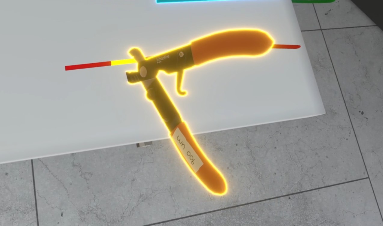
If the user attempts to strip too short or too long a section, an audible alert and a message — “Stripping too short/too long” — are displayed; the action is not completed, and the Quality of Execution score is affected.
During stripping, a waste piece is automatically generated and falls from the tool. The user must pick up this waste and place it in the trash bin before leaving the exercise, or their Environmental Responsibility score will be affected.
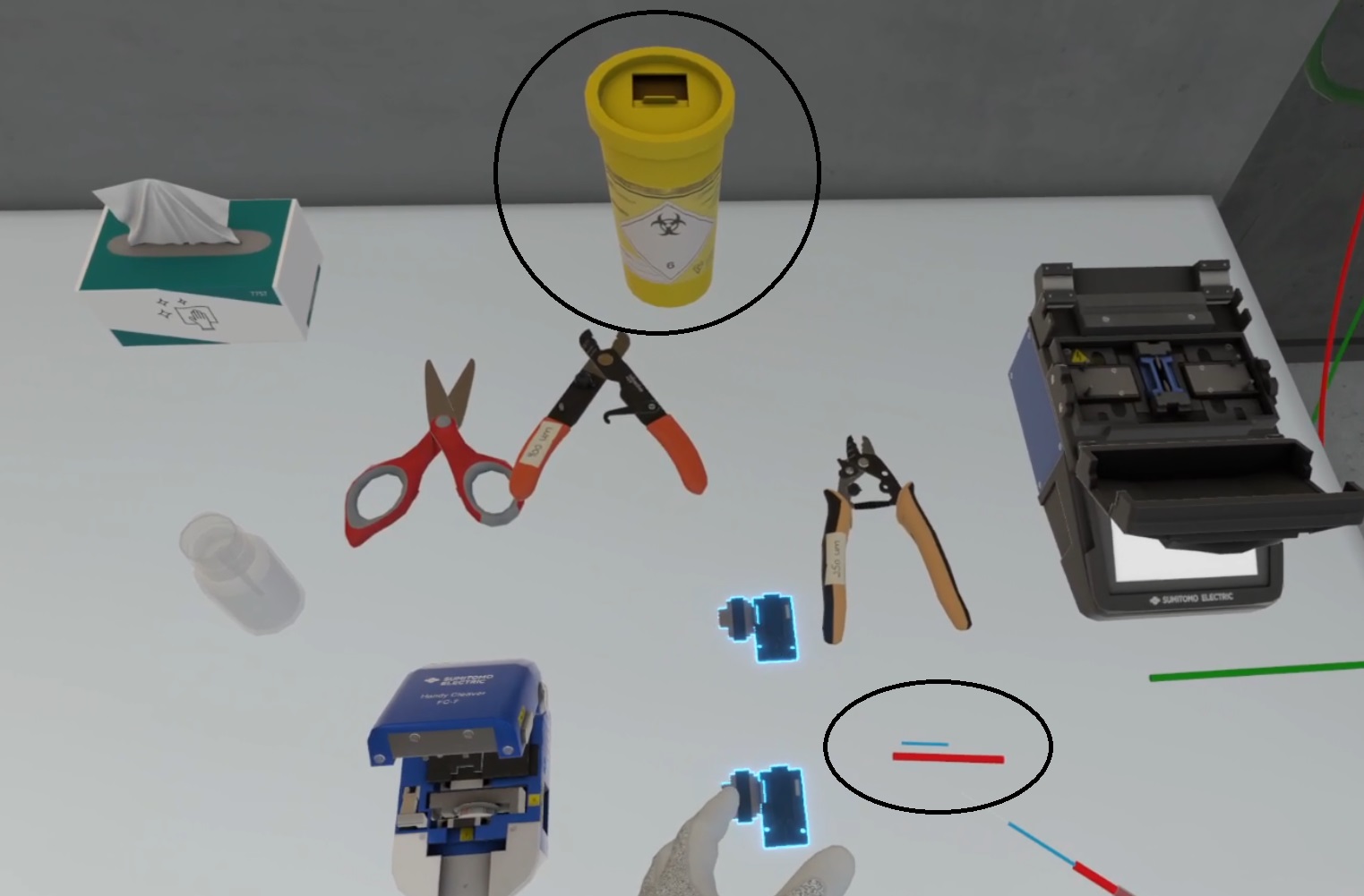
If the stripping step is forgotten, the Quality of Execution score is affected and the final welding will be of very poor quality.
Stripping the 250-micron Jacket
Then the user will take the 250-micron strippers and strip the end of the fiber to a length of 25 to 35 mm. image::MimbusHachetteVR/mh-connexion4.jpg[title="Using the 250-micron strippers", align="center", width=400]
The mechanisms and consequences are the same as in the previous step.
Cleaning with alcohol
The user must wet a lint-free wipe with isopropyl alcohol and carefully clean the fiber strand.
To do this, they must pick up a wipe and press it against the alcohol bottle to soak it — a sound effect will play, and a stain will appear on the wipe.

The user must touch the fiber strand with the wipe; a sound effect will play and the stain disappears from the wipe. image::MimbusHachetteVR/mh-connexion6.jpg[title="The user cleans the fiber strand", align="center", width=400]
If the user skips this step or forgets to moisten the wipe before cleaning, the Quality of Execution score will be affected, and the final splice will be of poor quality.
Positioning the Fiber Clamps
The user must pick up the fiber strand and place it onto a fiber clamp to hold it in position. The fiber automatically snaps into place magnetically when released near the correct area.
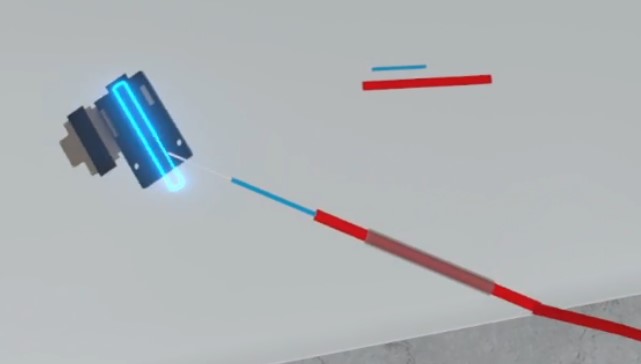
This step is mandatory before using the fusion splicer. If the user attempts to place a fiber without a clamp into the splicer, a message will appear: "You tried to put a fiber strand directly into the fusion splicer without using a clamp," and their score will be affected.
Placing the Fiber in the Cleaver
The user picks up the fiber (already positioned in a clamp) and places it in the fiber cleaver, then presses the Action button on the controller to perform the cut. An animation is triggered, resulting in a perfectly straight cleave.
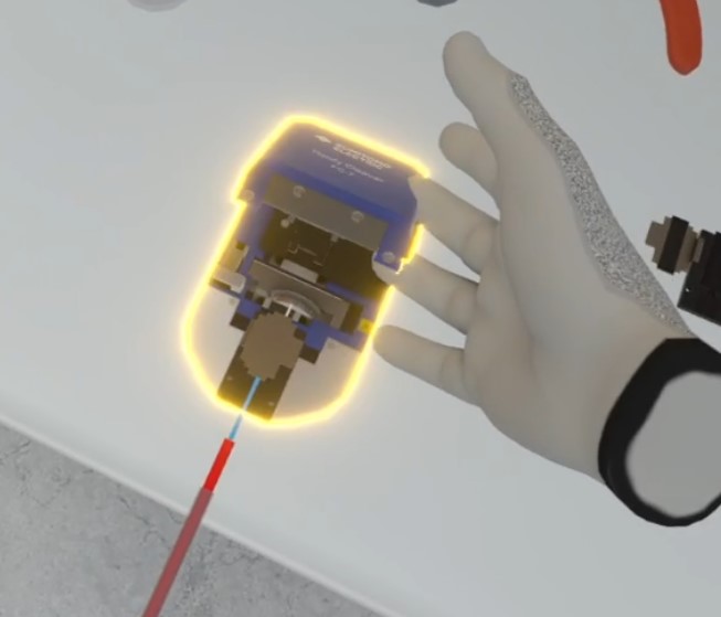
At this stage, the user can also use the scissors to make the cut, which will have the same consequence as skipping the cleaving step: a major impact on the Quality of Executgion score and a poor-quality splice.
Placing the Fiber in the Fusion Splicer
The user places the clamp containing the fiber strand into the fusion splicer.
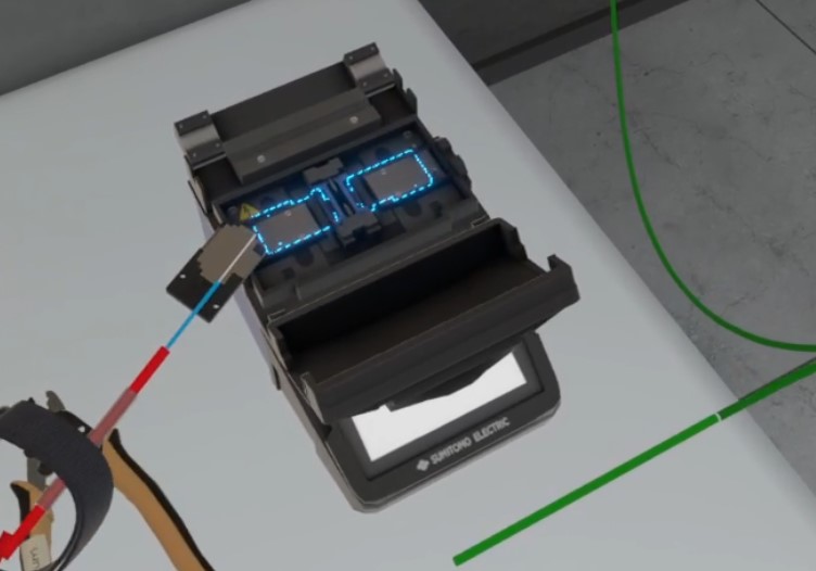
Stripping, Cleaning, Clamp Placement, and Cleaving the Second Fiber
The user repeats the same steps for the second fiber.
Fusion Splicing
When both fiber strands are in the splicer, the lid closes automatically.
The user must press the OK button on the screen to start the splicing process, triggering an animation. At the end of the animation, the message “Splice OK” appears, and both the splicer lid and clamps open.
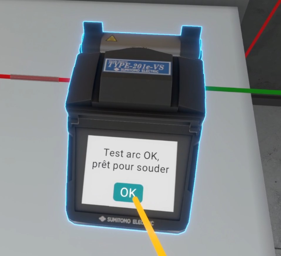
If the splice sleeve was not placed earlier, it will automatically appear at this stage, along with the message: "You forgot to use a splice protection sleeve. It has been automatically added to allow you to continue the scenario."
Placing the Splice Sleeve
Once the splice is complete, the user removes the fiber from the fusion splicer and slides the splice sleeve over the fused fiber strands.
The user positions their hand near the splice sleeve and presses the Action button on the controller; the protector automatically moves into place over the splice.
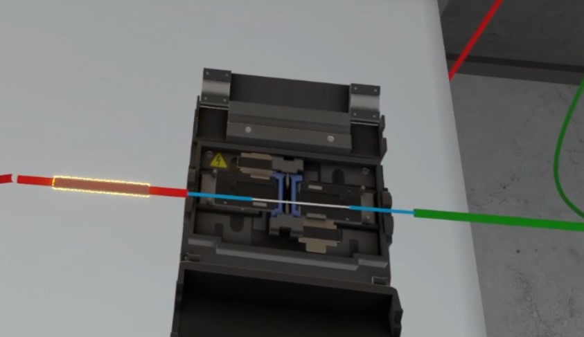
If the user skips this step, the next step will not be available.
Placing the Splice in the Oven
The user must take the fiber (with the splice sleeve properly positioned) and place it in the oven.
Placement occurs automatically via magnetism — the lid closes, and the heater starts.
A few seconds later, the lid opens automatically, and the user can retrieve the fiber.
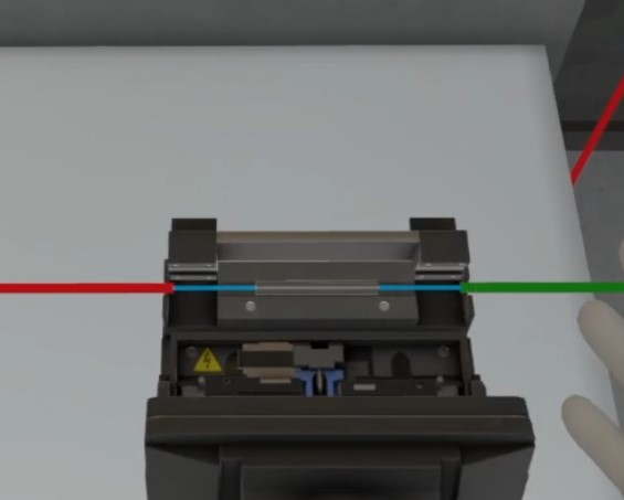
If the user fails to heat the splice sleeve, points are deducted from the Quality of Execution score.
Placing the Fiber in the Building Distribution Box
The user picks up the fiber at the splice point and places it into the building distribution box.
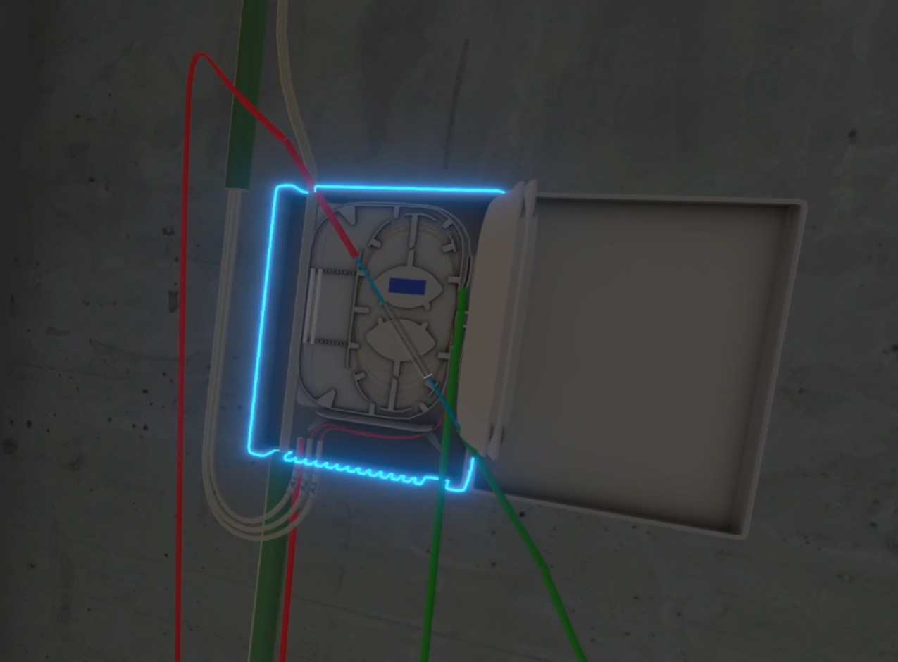
The fiber automatically locks into the correct position magnetically, and the cable is neatly secured.

Splice Inspection 1/3
The user moves to the building distribution box cabinet, disconnects cable A1, and connects the tester pen in its place.
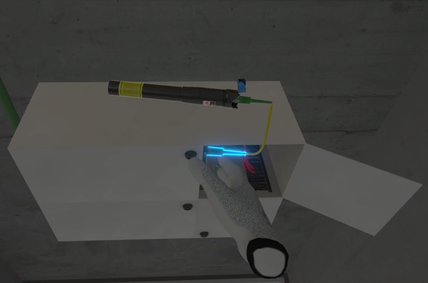
If the user connects the tester pen to the wrong fiber, points are deducted from the Quality of Execution score. An audible alert sounds, accompanied by the message: “You connected the laser test pen to the wrong fiber.”
If the user points the tester pen toward their eyes, points are deducted from the Safety score.
Splice Inspection 2/3
The user must go to apartment A1 to verify that the fiber connection is functional up to the ONT (Optical Network Terminal).
The user moves to apartment A1, where the ONT is located near the entrance.
The subscriber cable is disconnected nearby. Depending on the quality of the previous steps, the user may or may not see light emitting from the fiber.
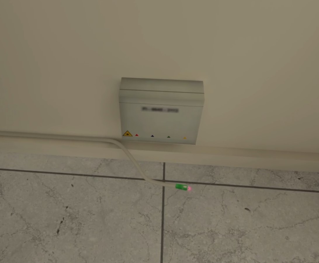
If there is no signal loss (light is visible at the end of the cable), the following message appears: “Well done! There is no light leakage at your splice. You can now see light at the connector near the ONT.”
If a leak is detected (no light is visible), the following message appears: “Error: There is light leakage at your splice. This is why you don’t see light at the connector near the ONT.”
If the user skips this inspection step, it has a minor impact on the Quality of Execution score.
Splice Inspection 3/3
The user must return to the building distribution box, disconnect the tester pen, and reconnect the subscriber’s cable to its original position.
If this step is skipped, the user’s score is affected.
Exiting the Exercise
To finish, the user must return to the main lobby in front of the entrance door to be teleported to the results screen. Note that the user may exit the exercise at any time by going to this area.

5.4.3. Exercise Evaluation Criteria
![]() Safety: Checks whether the user’s behavior follows proper safety practices (tester pen).
Safety: Checks whether the user’s behavior follows proper safety practices (tester pen).
![]() Quality of Workmanship: Validates the result. The score decreases if the user does not follow the correct procedure.
Quality of Workmanship: Validates the result. The score decreases if the user does not follow the correct procedure.
![]() Environmental Responsibility: Verifies that all waste materials have been properly disposed of in the trash.
Environmental Responsibility: Verifies that all waste materials have been properly disposed of in the trash.
6. Agriculture Module
6.1. Viticulture
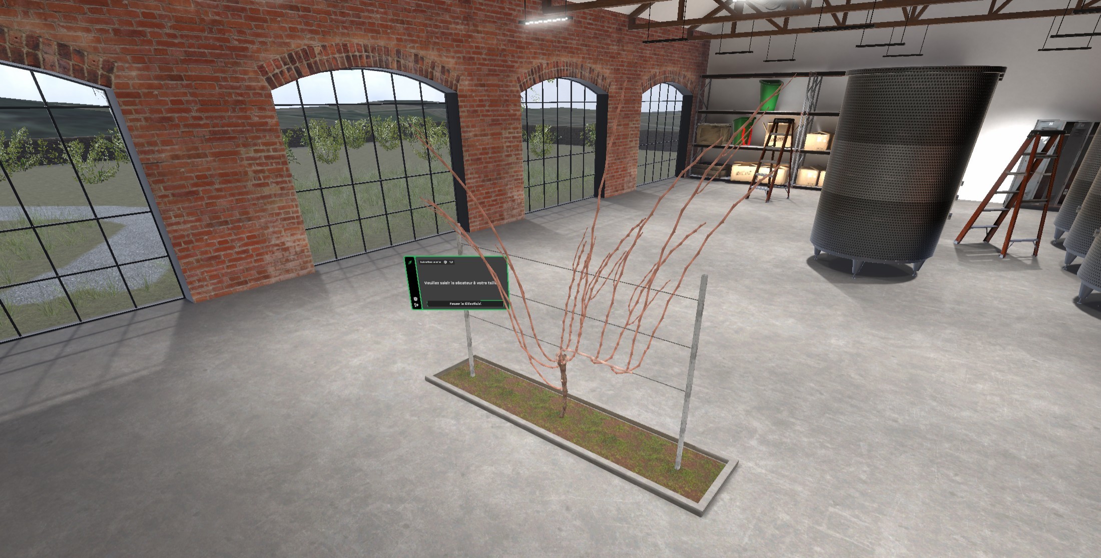
The objective of this exercise is to prune a vine using the simple cane pruning technique.
6.1.1. Exercise Plan
To validate the exercise, the user must perform the actions in the following order:
-
(Optional tutorial) – Pick up the pruning shears
-
(Optional tutorial) – Bring the shears close to a branch to align magnetically
-
(Optional tutorial) – Cut a branch
-
Prune the suckers
-
Cut the old fruiting cane at its base
-
Cut the new fruiting cane to 8 healthy buds
-
Cut the new spur to 2 healthy buds
-
Remove dead stubs and unwanted shoots
-
Tie the new fruiting cane to a wire
6.1.2. Scenario Overview
Briefing
The scenario begins with a briefing that the user must confirm by clicking the Continue button to proceed.
As a grape grower, you are going to prune a grapevine using the technique known as simple cane pruning.
The exercise starts with a few steps to help the user become familiar with the pruning shears and their functionality. The tutorial can be skipped at any time by clicking the Skip Tutorial button located below the instructions. The scenario will then continue directly to the sucker-pruning stage.
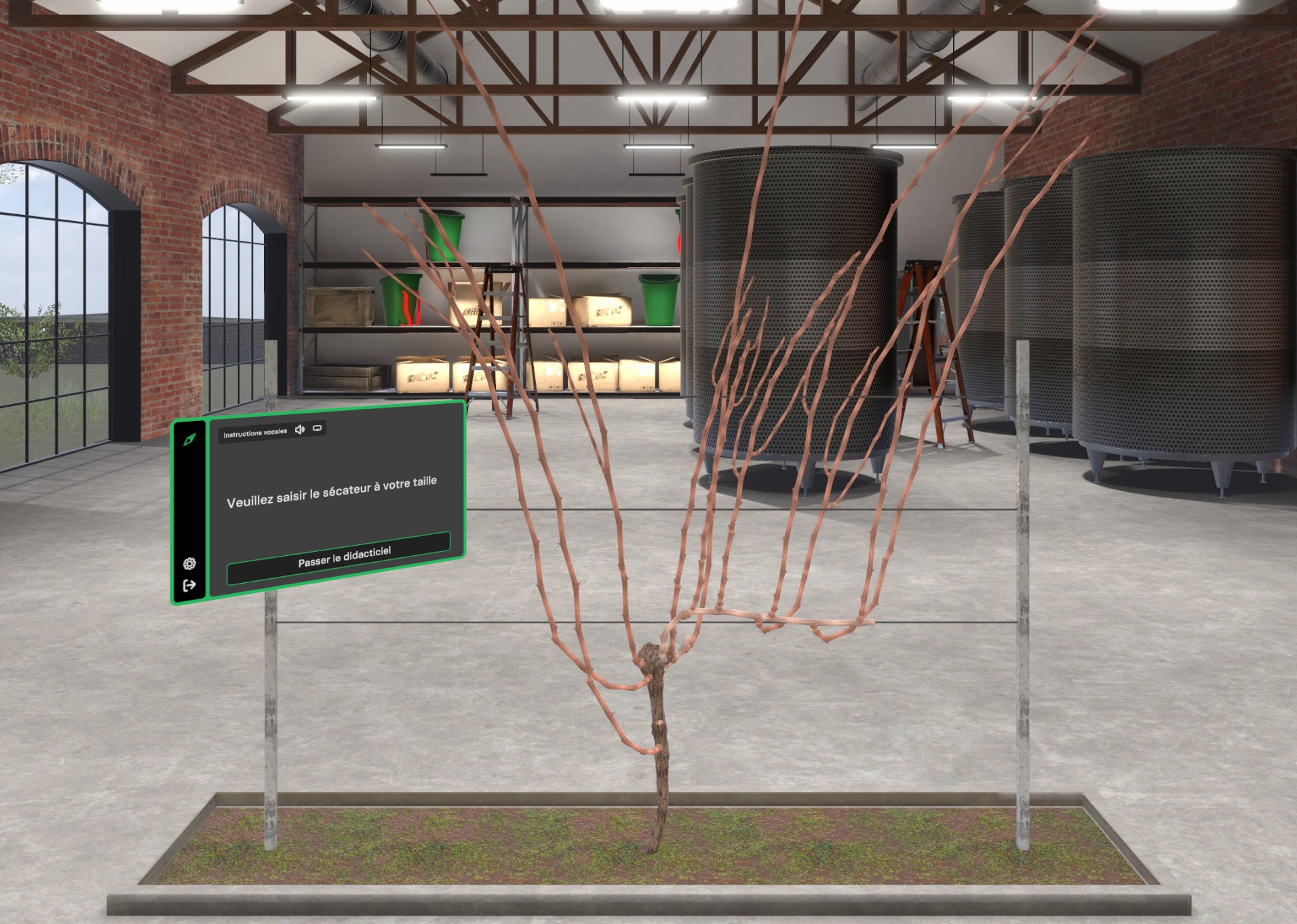
Tutorial - Pick up the pruning shears
Please grab the pruning shears in front of you.
The shears are located at the player’s belt height, slightly in front. Simply tilt your head forward and grasp them by placing your hand on the tool and holding the VR controller button used to grab an object.
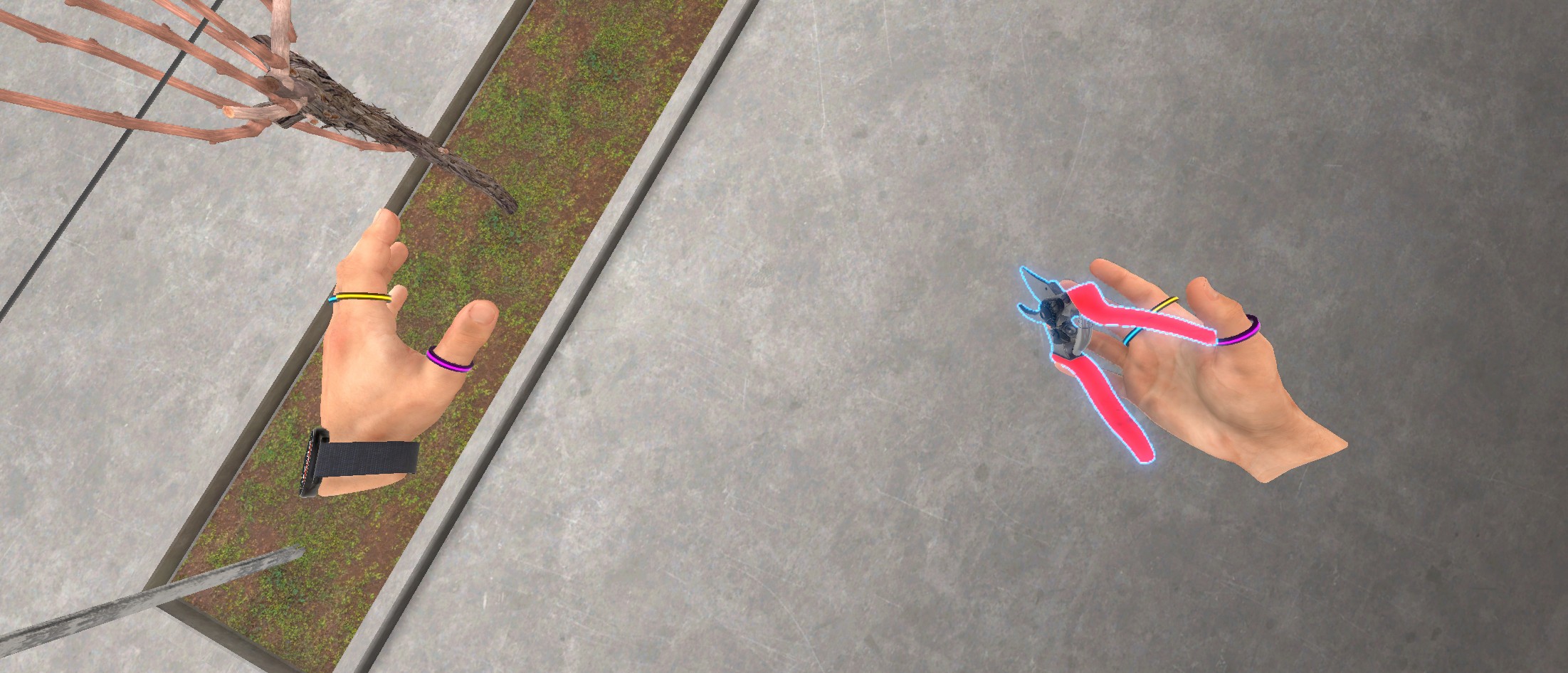
Tutorial - Bring the shears close to a branch and magnetically lock them
Bring the pruning shears close to a branch and press the A or X button on your controller to snap the pruning shears to it.
Once the shears are in hand, bring them toward a vine branch in front of the user. Press and hold the A button (right hand) or X button (left hand) on the VR controller to magnetically lock the shears to the branch. When the shears touch the branch, a black circle indicator appears to show that you can “magnetically lock” the shears to the branch by pressing the indicated button.
This improves precision during pruning and lets you slide your hand along the branch to reposition the shears easily.
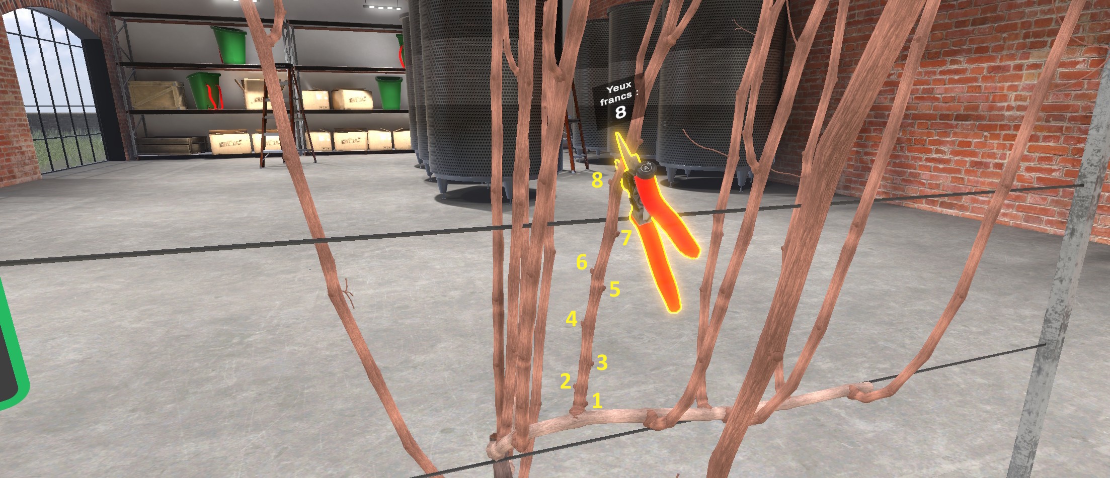
A small panel indicates the number of healthy buds left after pruning. This refers to the number of well-formed, visible buds on the branch that will be capable of producing a new shoot next season.
Tutorial - Cut a branch
Press the interaction trigger to cut the branch.
With the shears magnetically locked, pressing the controller’s interaction trigger will prune the branch at the shear blades. This completes the tutorial. Wait a few seconds for the vine to reset, then you can begin the simple cane pruning exercise.
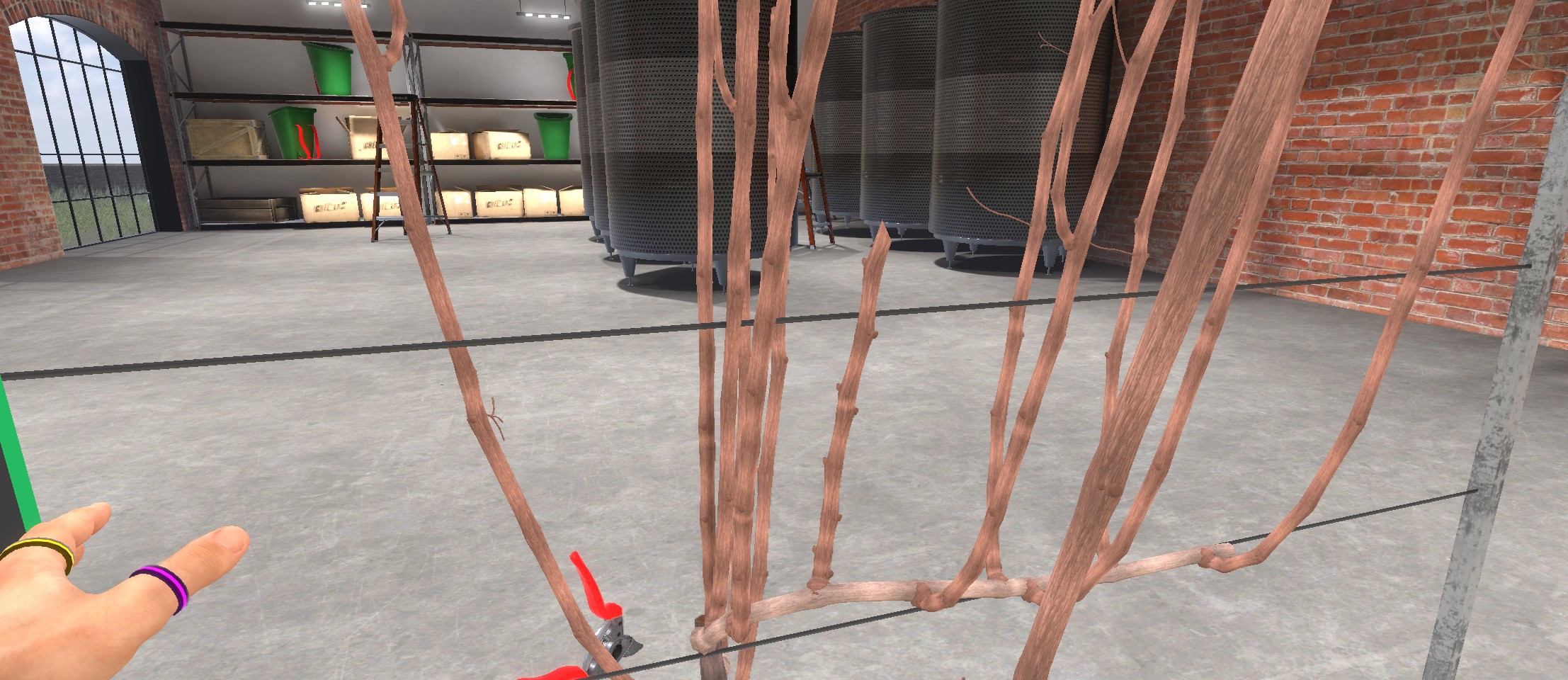
Pruning Sequence
The simple cane pruning of the vine will be carried out step by step. At each step, instructions are displayed on a panel to the left of the vine. A secondary panel on the right provides additional information explaining which branches to prune and how to identify them.
A Show me where to prune button highlights the exact areas to cut. Each click on this button applies a penalty to the Autonomy metric.
Labels are also placed near the vine to help the user identify the referenced branches.
Pruning the Suckers
Prune the sucker branches to their base.
Suckers are useless shoots that grow from the old wood and take the plant’s energy without producing grapes.
The first step is to identify and prune the suckers. Suckers are branches that grow directly from the old trunk wood rather than from a branch of the previous year.

Pruning the suckers at their base means cutting them just below the first bud on the branch.
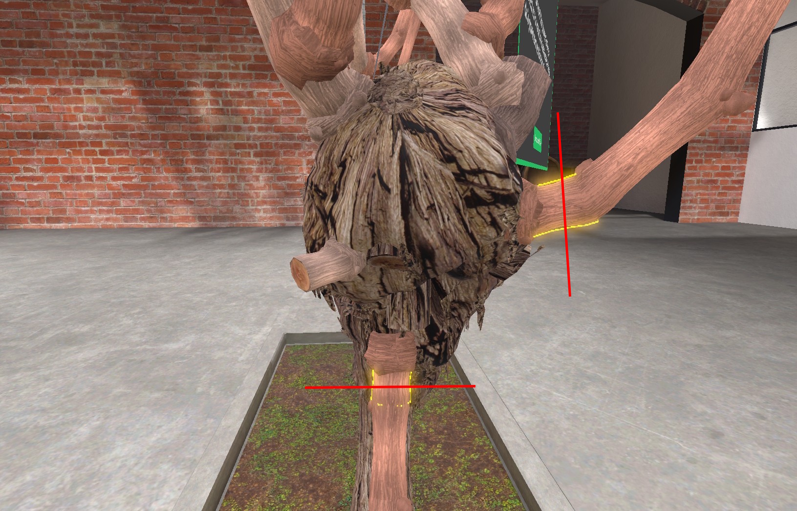
Pruning the Old Fruiting Cane
Prune the old cane at its base.
The fruiting cane is a branch that was pruned long last winter to support the shoots bearing this year’s grapes.
Because the grapevines are generated randomly, there are two possible configurations: the fruiting cane and spur from last year may be separate, or they may both grow from the same spur.
Separate Fruiting Cane and Spur
If the fruiting cane and spur are separate, simply cut the old fruiting cane (shown in green) at its base.

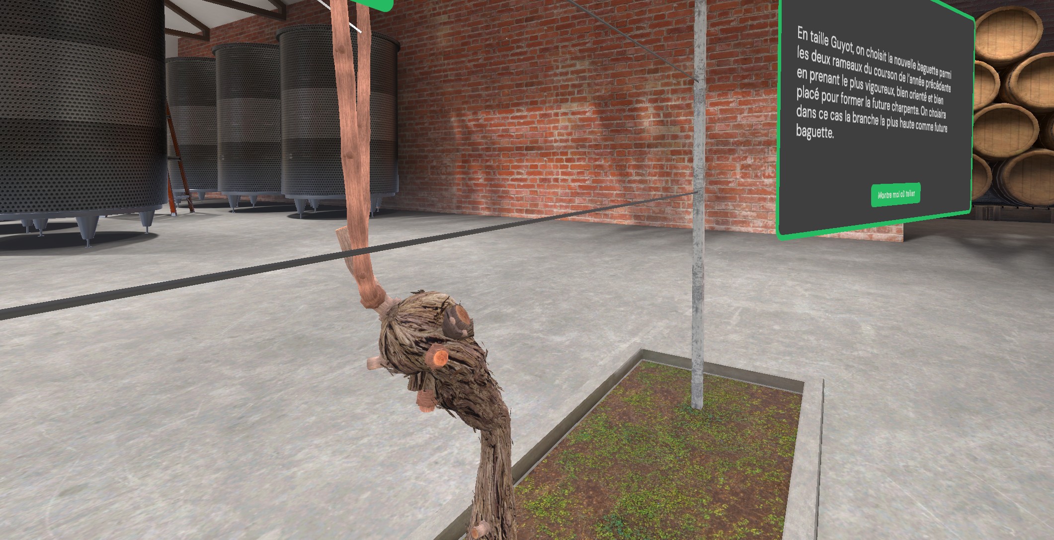
Fruiting Cane and Spur on the Same Spur
If the fruiting cane and spur are both on the same old spur, proceed carefully and cut the old spur at the base of the fruiting cane (shown in green), taking care not to cut the future spur (shown in blue).
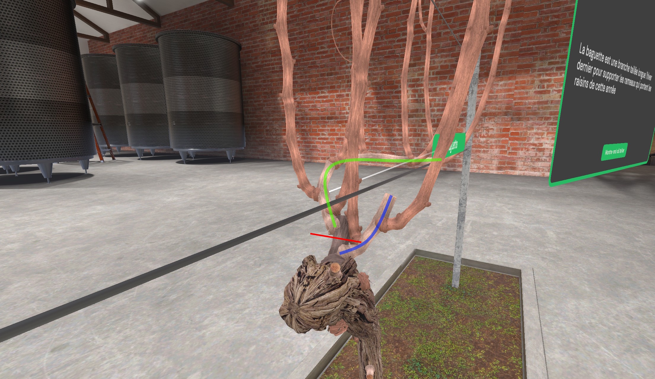
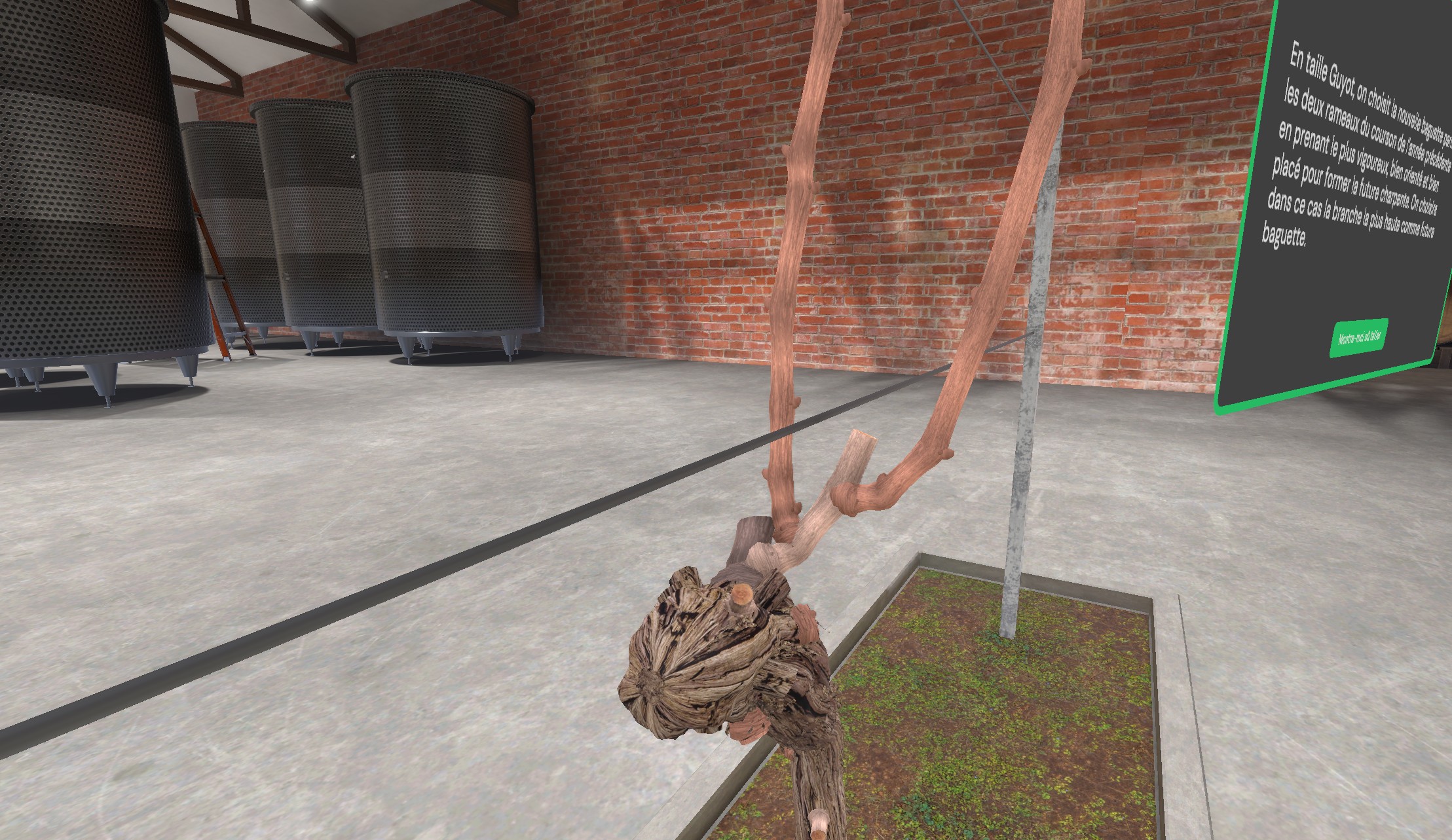
Pruning the New Fruiting Cane
Cut the new fruiting cane to 8 healthy buds.
In the simple cane pruning system, the new fruiting cane is chosen from the two shoots of last year’s spur, selecting the stronger one that is well oriented and well positioned to form the next season’s structure. In this case, the higher branch will be chosen as the new fruiting cane.
Using the pruning shears’ indicator window, which shows the number of buds remaining, prune the new fruiting cane to 8 healthy buds (that is, leaving 8 buds).
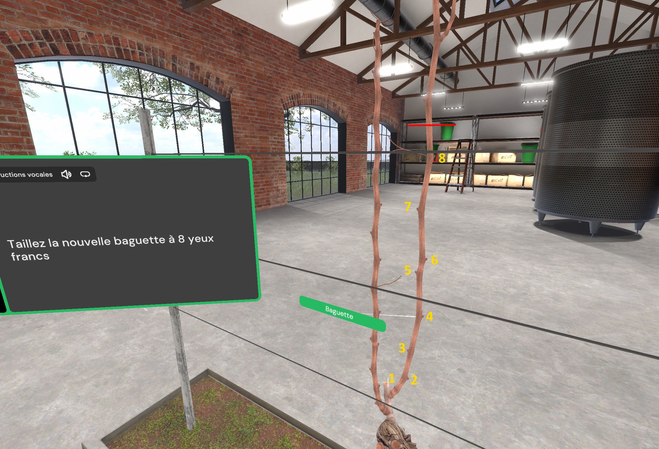
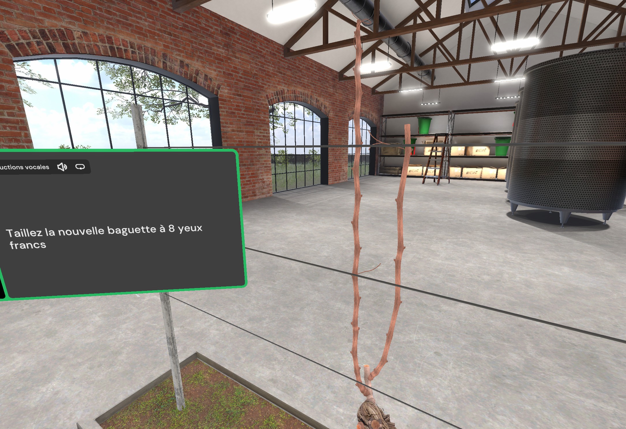
Pruning the New Spur
Cut the new spur to 2 healthy buds.
In the simple cane pruning system, the new spur is selected from the shoots of last year’s spur, keeping the lowest one that is well oriented and vigorous, to ensure future production and renewal of the fruiting cane.
Using the pruning shears’ indicator window, which shows the number of buds remaining, prune the new spur to 2 healthy buds (that is, leaving 2 buds).
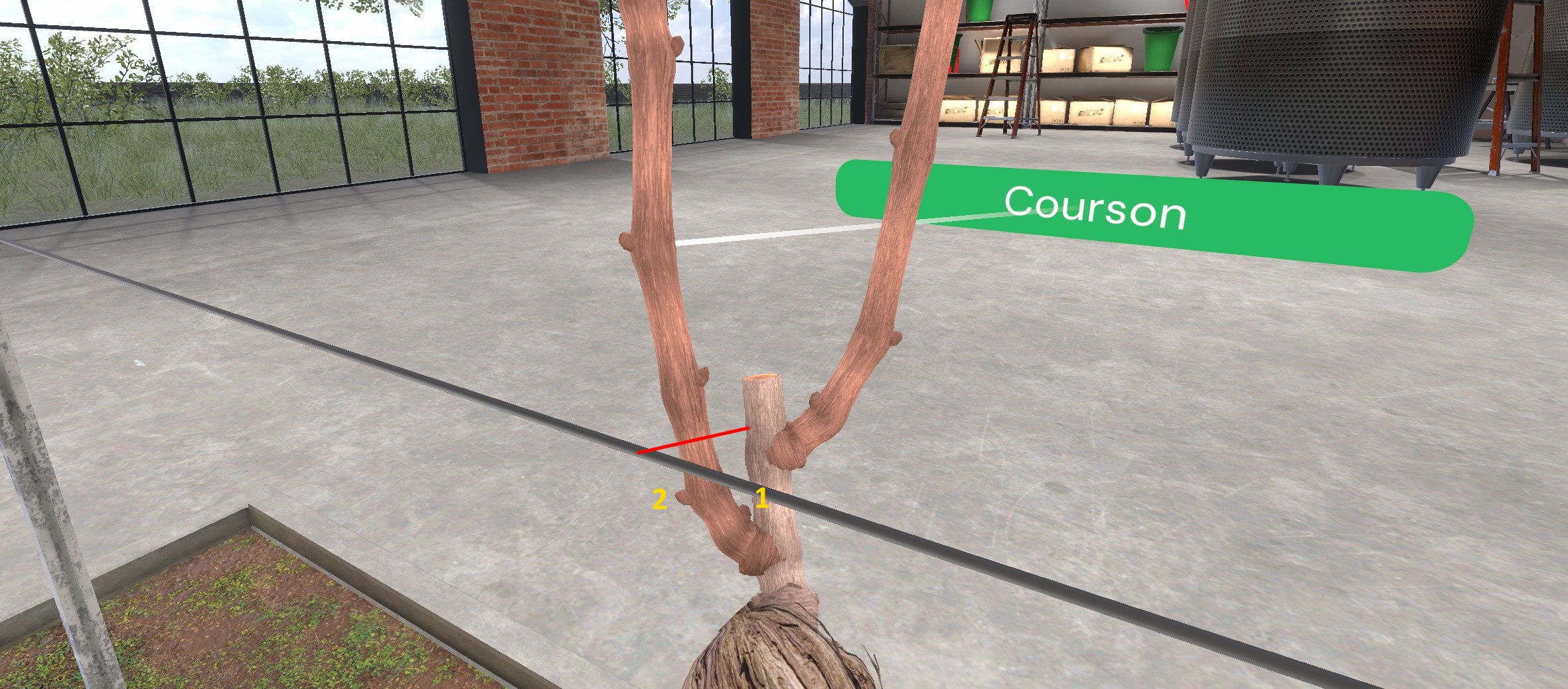

Pruning Dead Stubs and Unwanted Shoots
Cut the remaining dead stubs on the old wood from previous years and remove any remaining unwanted shoots.
Dead stubs are remnants of branches pruned in past seasons on the old wood. In the simple cane pruning system, they are removed to prevent disease and promote clean healing.
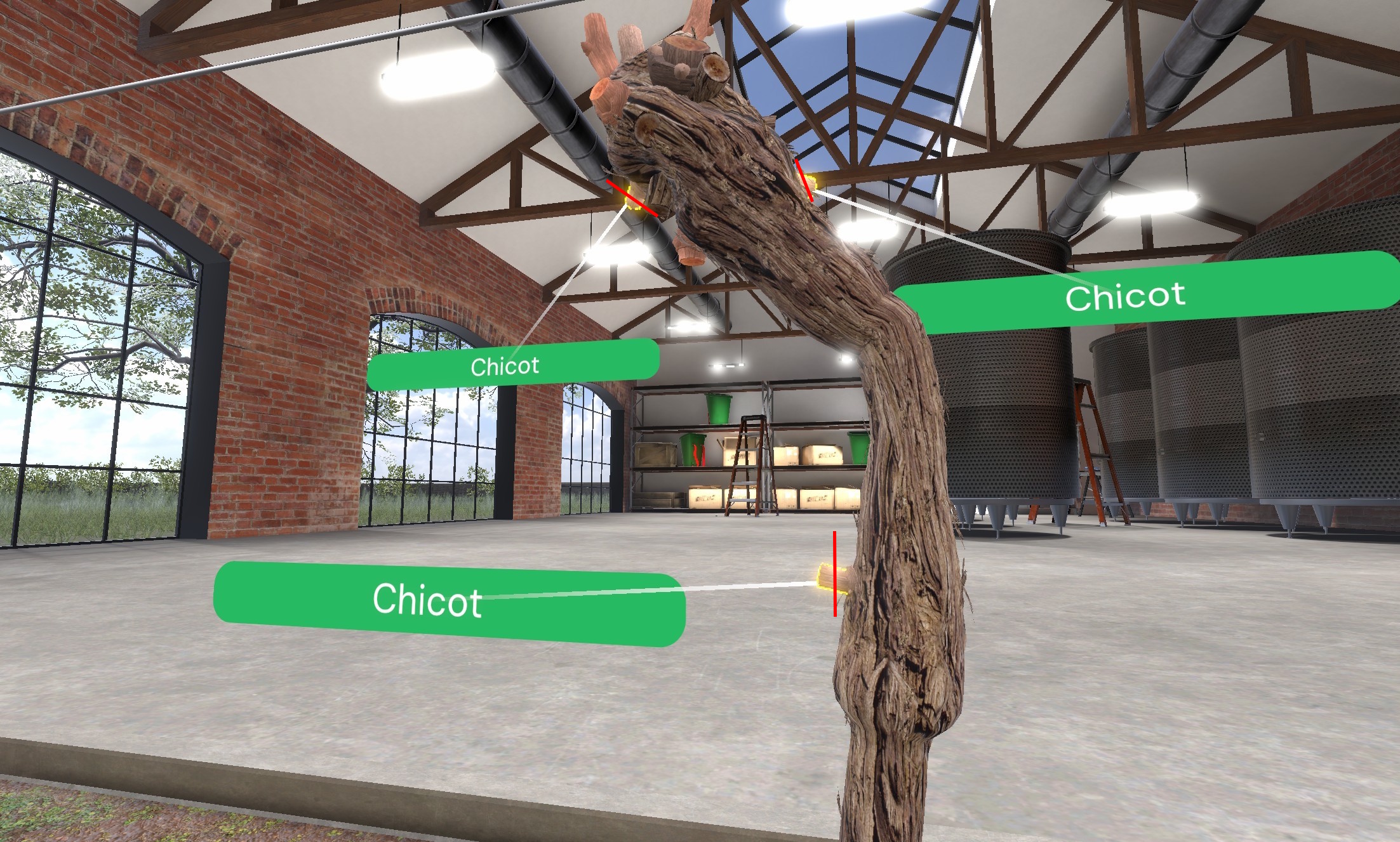

Unwanted shoots (also called “water sprouts”) are small premature shoots that emerge from the main branches in spring and generally do not bear fruit.


Tying the New Fruiting Cane
Grab the new fruiting cane and release it horizontally onto the lower wire to tie it down.
The new fruiting cane has been pruned; it will serve as the base from which next year’s fruit-bearing shoots will grow. It must now be positioned horizontally to encourage vertical growth of the future shoots. To do this, bring one hand close to the cane and hold the grab button on the VR controller to take hold of it.
Then, using the transparent preview of the branch as a guide, position the cane horizontally on the lowest wire and release the button.
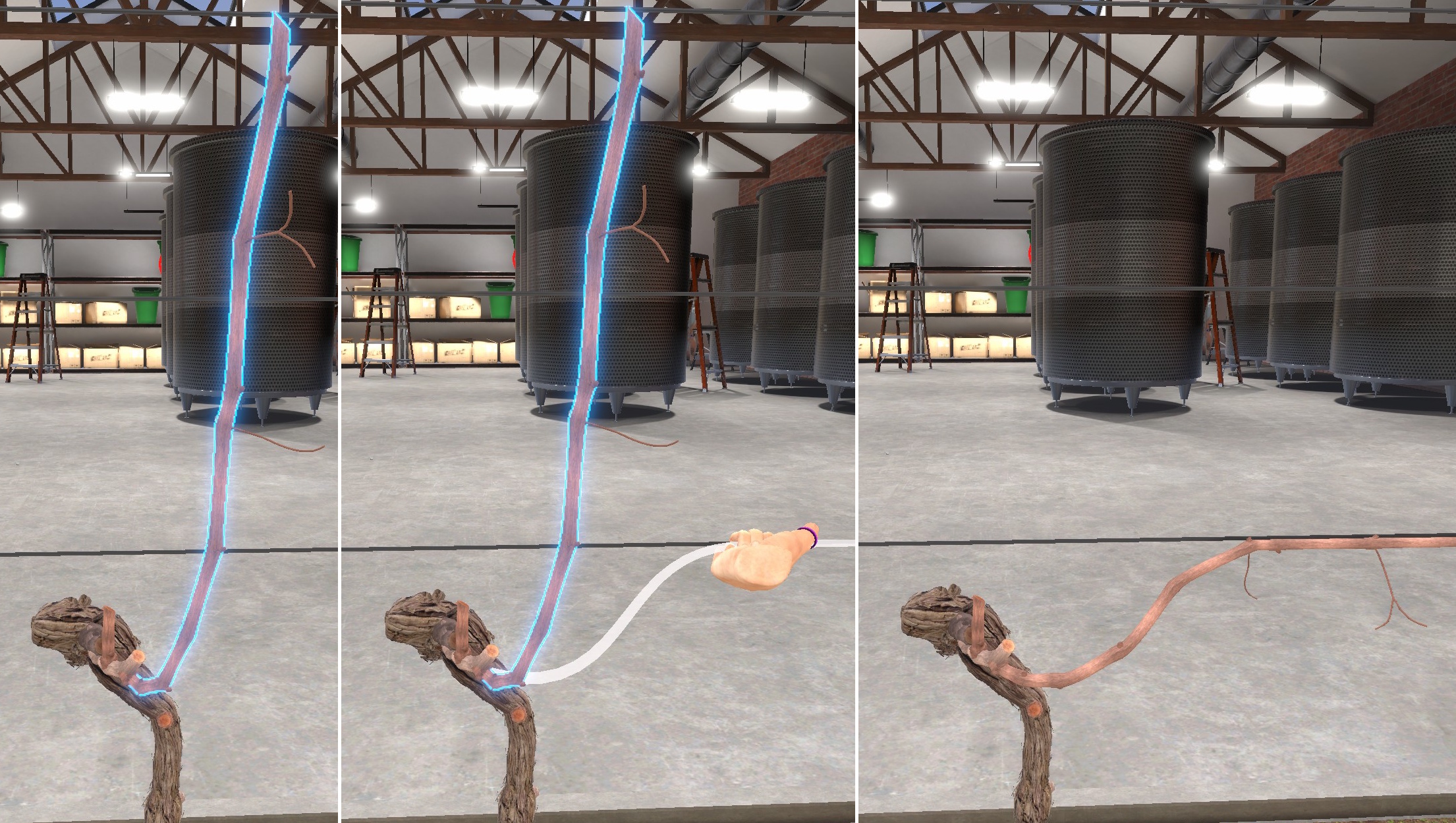
Results
You can now observe the effects of your pruning on the regrowth of the vine.
The simple cane pruning is now complete.
The vine will take a few seconds to grow into its early-summer state, allowing you to visualize the results of your pruning.
Click the View Results in the Lobby button to teleport to the results screen, where you can review detailed feedback and your final score.

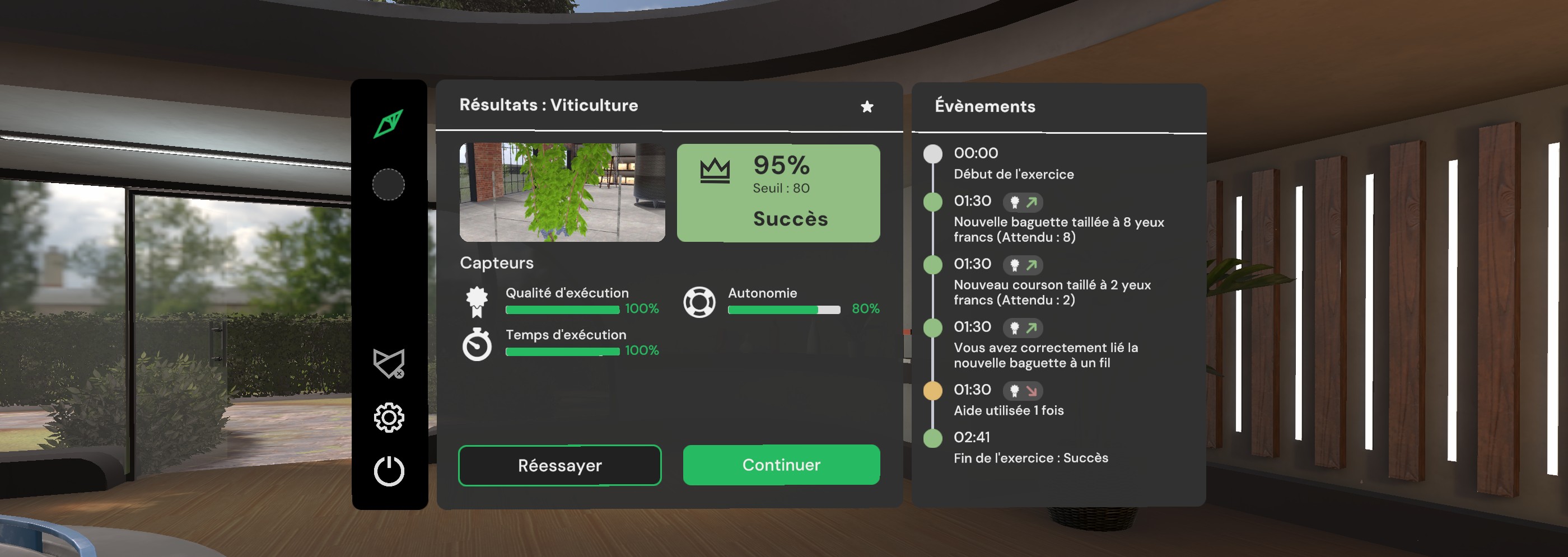
6.1.3. Exercise Evaluation Criteria
![]() Execution quality: Assesses adherence to the single-Guyot pruning procedure.
Execution quality: Assesses adherence to the single-Guyot pruning procedure.
![]() Autonomy: Evaluates the user’s ability to complete the exercise without assistance. The score decreases if the user requests help.
Autonomy: Evaluates the user’s ability to complete the exercise without assistance. The score decreases if the user requests help.
![]() Execution Time: Measures the time spent completing the exercise.
Execution Time: Measures the time spent completing the exercise.
This is the end of the Discover User Guide