1. Introduction
This document lists the different functionalities available in the MIMBUS CONSTRUCT simulator.
We will first explain the generic features common to all our simulators.
Secondly, we will detail each instruction associated with a sequence of the simulator, that is to say how to accomplish the task assigned by the system in order to proceed to the next step during the simulation.
2. General Operation
2.1. Main Menu
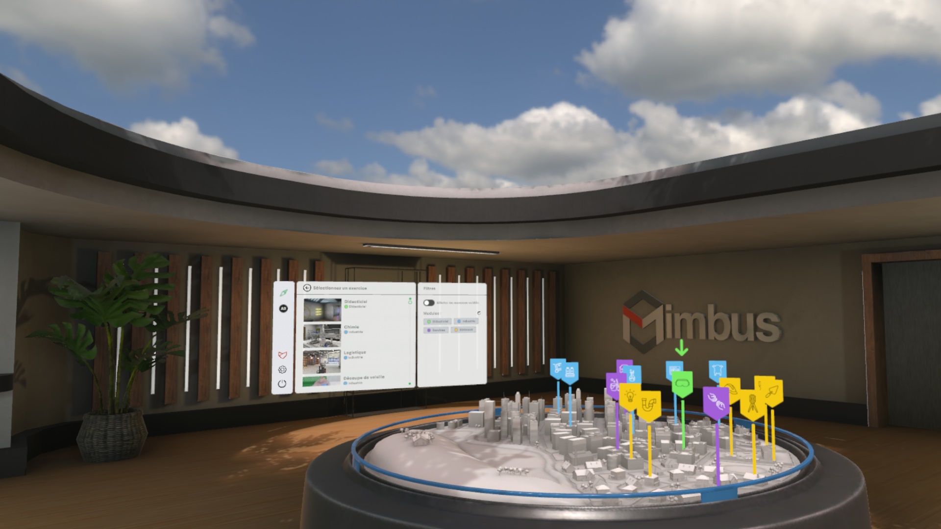
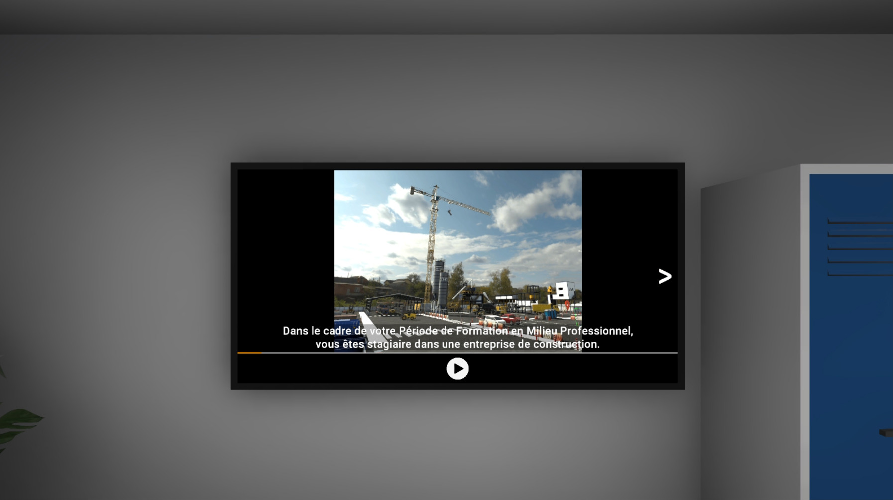
When launching the application, the user is in a main room called the "reception hall", where a screen displays the simulator’s main menu.
The main menu allows the user to authenticate, select an exercise to perform, and view their results. At the end of each exercise, they will be teleported back to this room.
2.1.1. User Selection
-
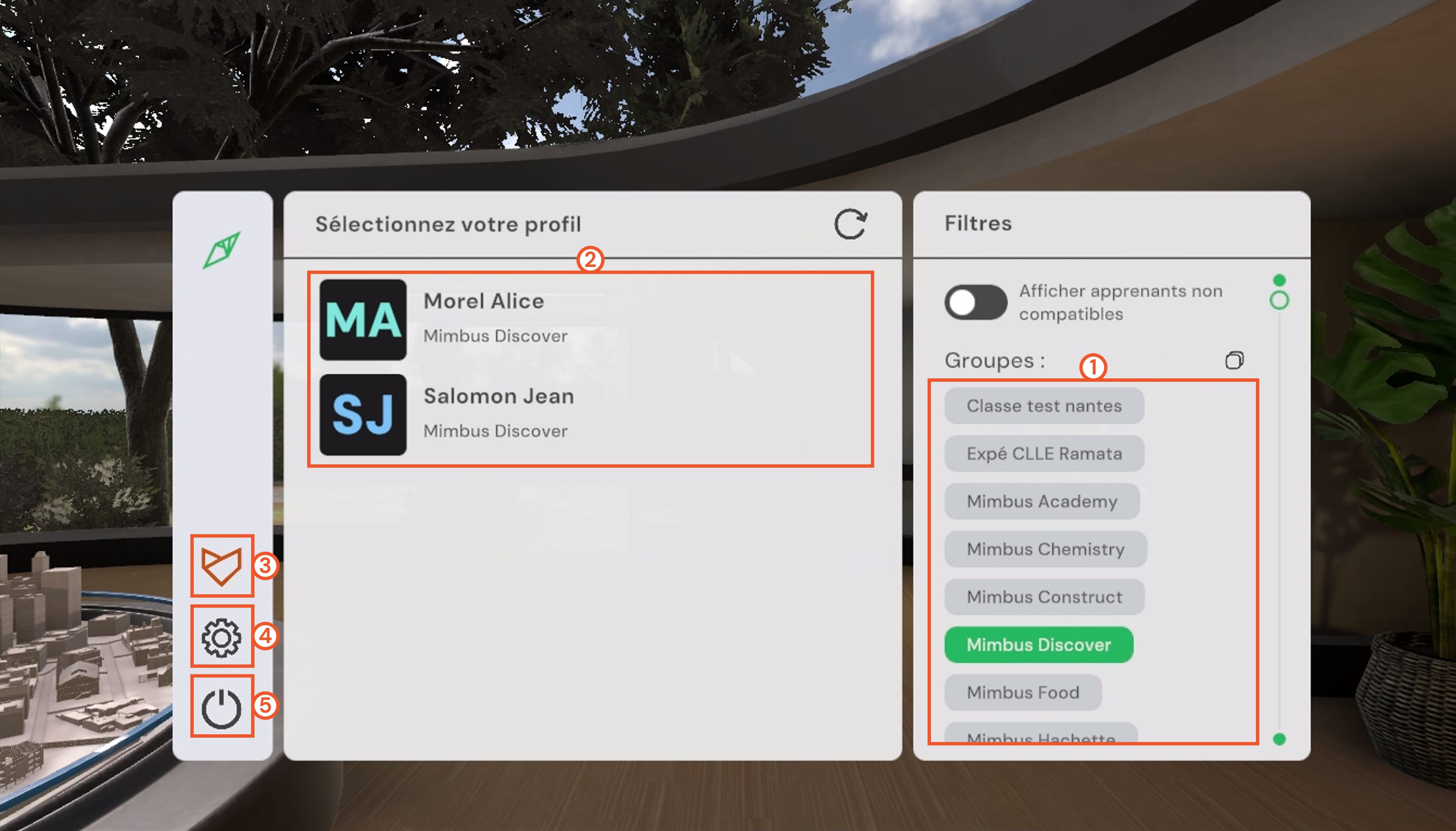
Groups menu: allows filtering users by group. If no group is selected, all available users are displayed.
-
Users menu: allows selecting the user to authenticate.
-
VULCAN connection button: allows connecting or disconnecting to the VULCAN platform.
-
Settings button: allows opening the settings screen.
-
Exit button: allows exiting the application.
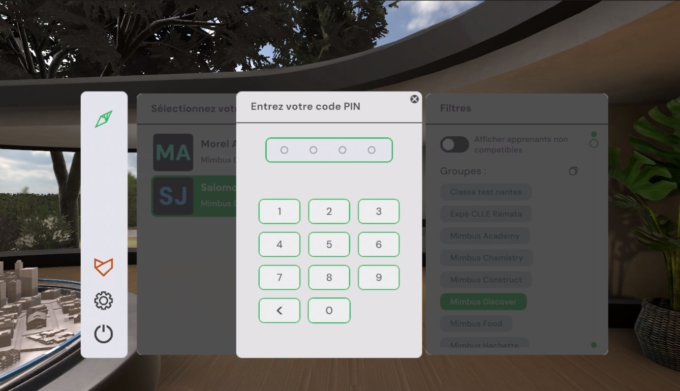
First, it is necessary to choose a user from those available on the main screen. A simple click on the user’s name displays a window in which you must enter their PIN code (four-digit number), configured in VULCAN.
The user can use the Groups filters on the right, allowing them to display only users from one or more classes created in VULCAN.
It is possible to display all users present in your VULCAN organization. However, those who are not assigned to a learning path corresponding to your simulator will appear grayed out. It will not be possible to log in with them on this simulator.
In offline mode, a demonstration user will be automatically selected.
2.1.2. Exercise Selection
-
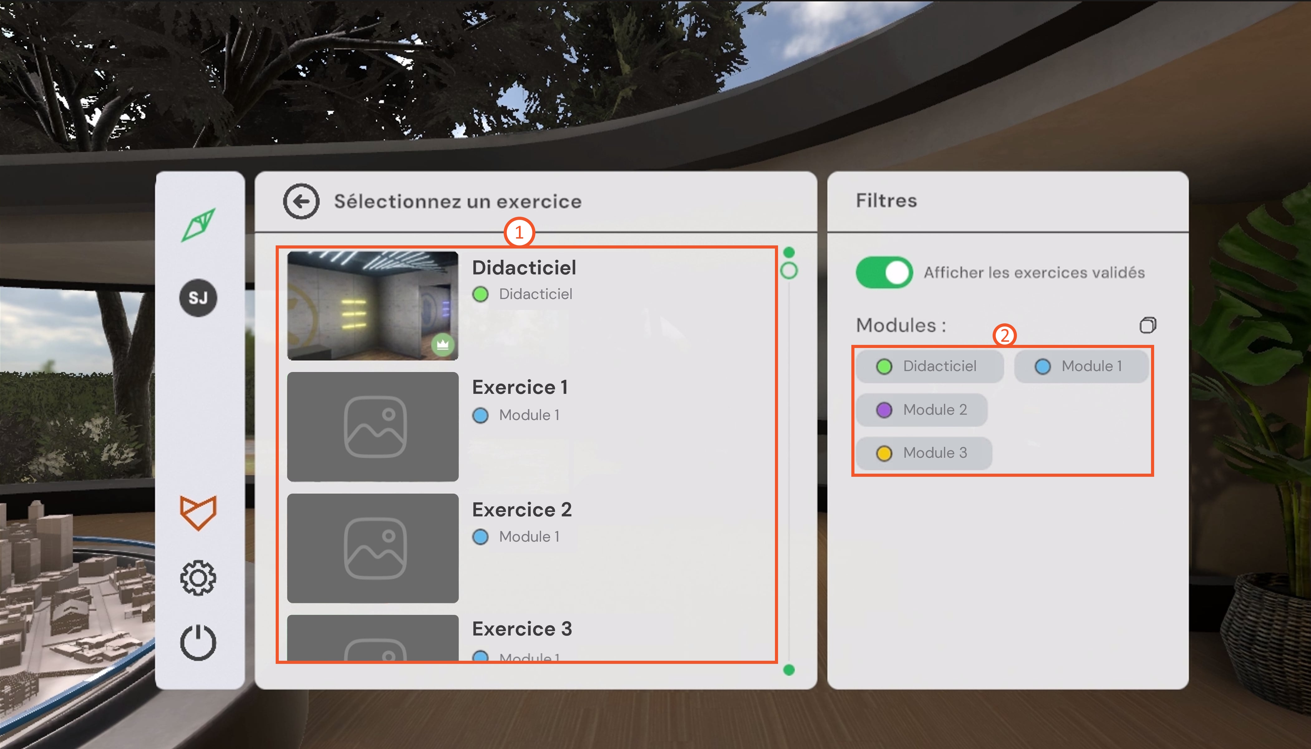
Exercise menu: allows selecting the exercise to launch.
-
Modules menu: allows filtering exercises by module. If no module is selected, all available exercises are displayed.
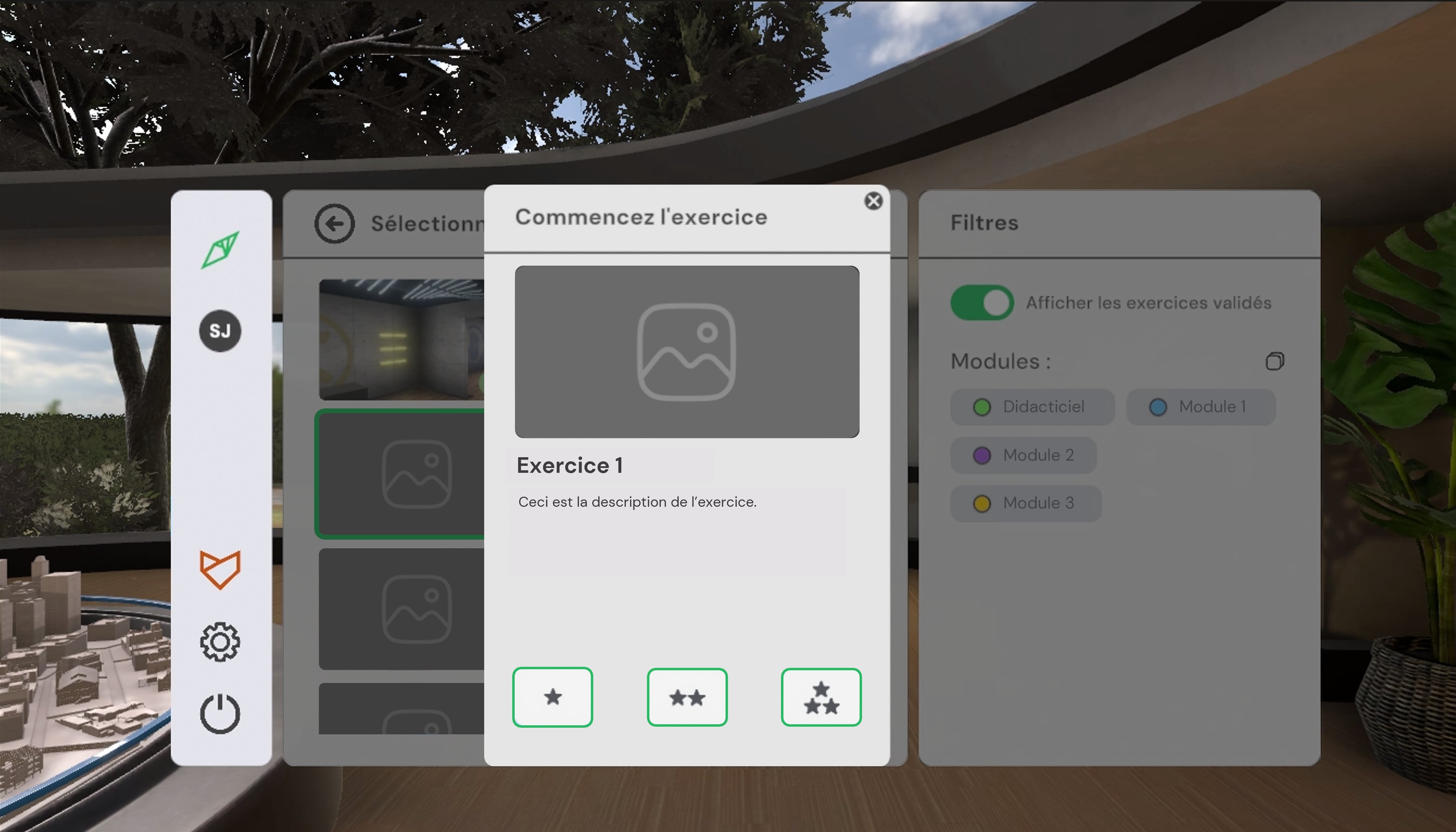
This page displays the available exercises. A first click on an exercise displays its description. A second click validates the choice and launches the exercise. The tutorial allows you to familiarize yourself with the controls using a simplified scenario.
The user can use the Modules filters on the right to display only exercises from one or more categories.
In the exercise list, those already validated by the user are identified by a white crown in a colored circle. If connected to VULCAN, they can also choose to display only unvalidated exercises by deactivating the Show validated exercises button. Activating it allows viewing all exercises assigned to their group.
2.1.3. Difficulty Mode Selection
For compatible simulators, when selecting the exercise, the user can choose the difficulty level: Beginner, Advanced, or Expert. Depending on the exercises, the difficulty modifies the instructions and objectives. A click on the difficulty level launches the exercise. Already validated levels are identified by a white crown in a colored circle. For simulators that do not offer difficulty levels, a click on the Start button directly launches the exercise.

2.1.4. Results Screen
-
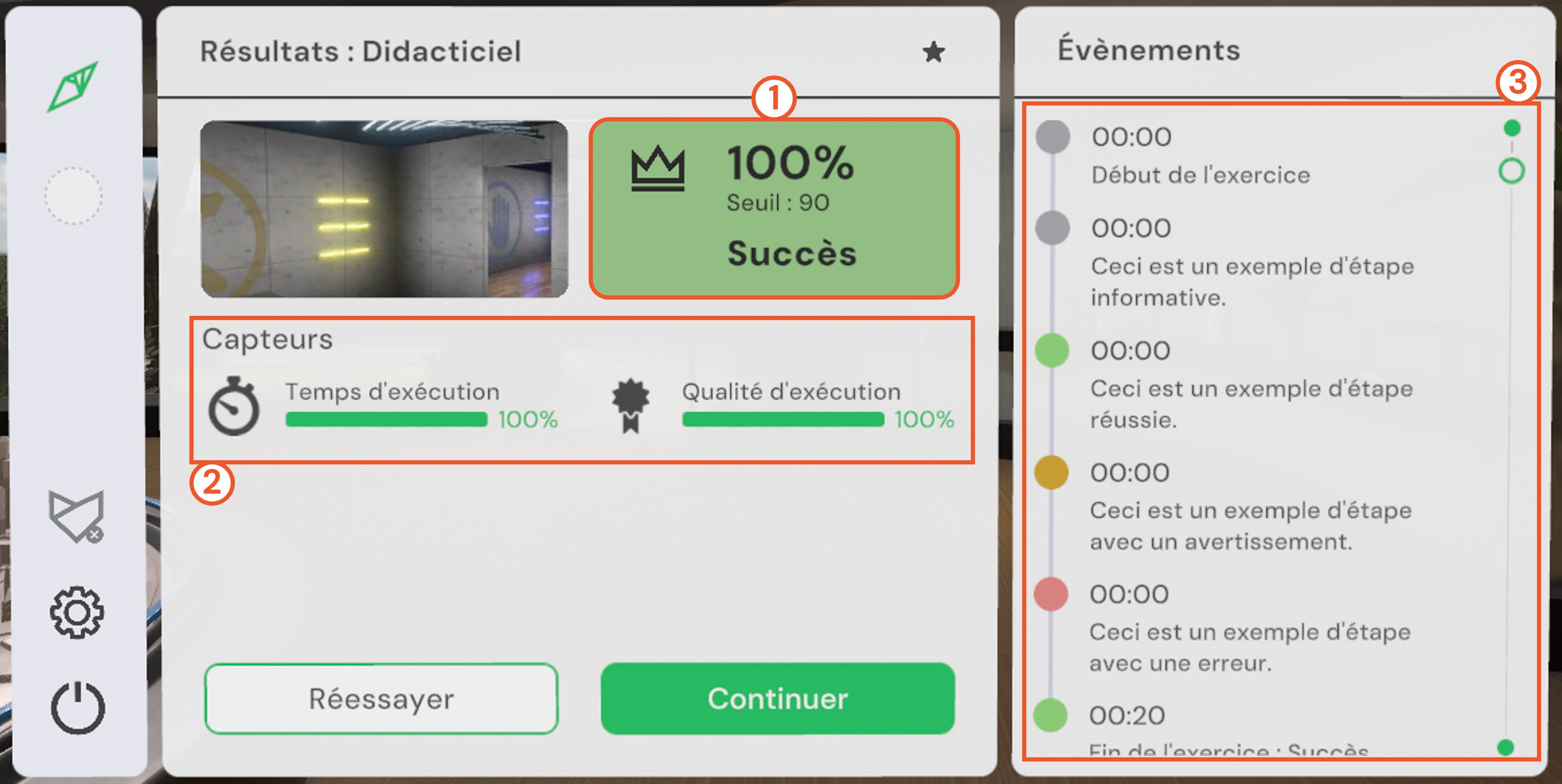
Exercise result: displays the overall score as a percentage (average of sensor scores, weighted by their respective coefficients defined in VULCAN), as well as whether the exercise was validated and its validation threshold.
-
Sensor results: display the evaluation criteria specific to each exercise.
-
Event history: indicates all significant events that occurred during the exercise. The timecode corresponds to the moment of the event, expressed in minutes and seconds elapsed since the start of the exercise.
At the end of the exercise, the user is teleported to the results screen, where they can view the overall summary, sensor details, and events that occurred during the exercise.
2.1.5. Settings Screen
From the home screen and in each simulator, the user can access the settings by clicking on the gear icon.
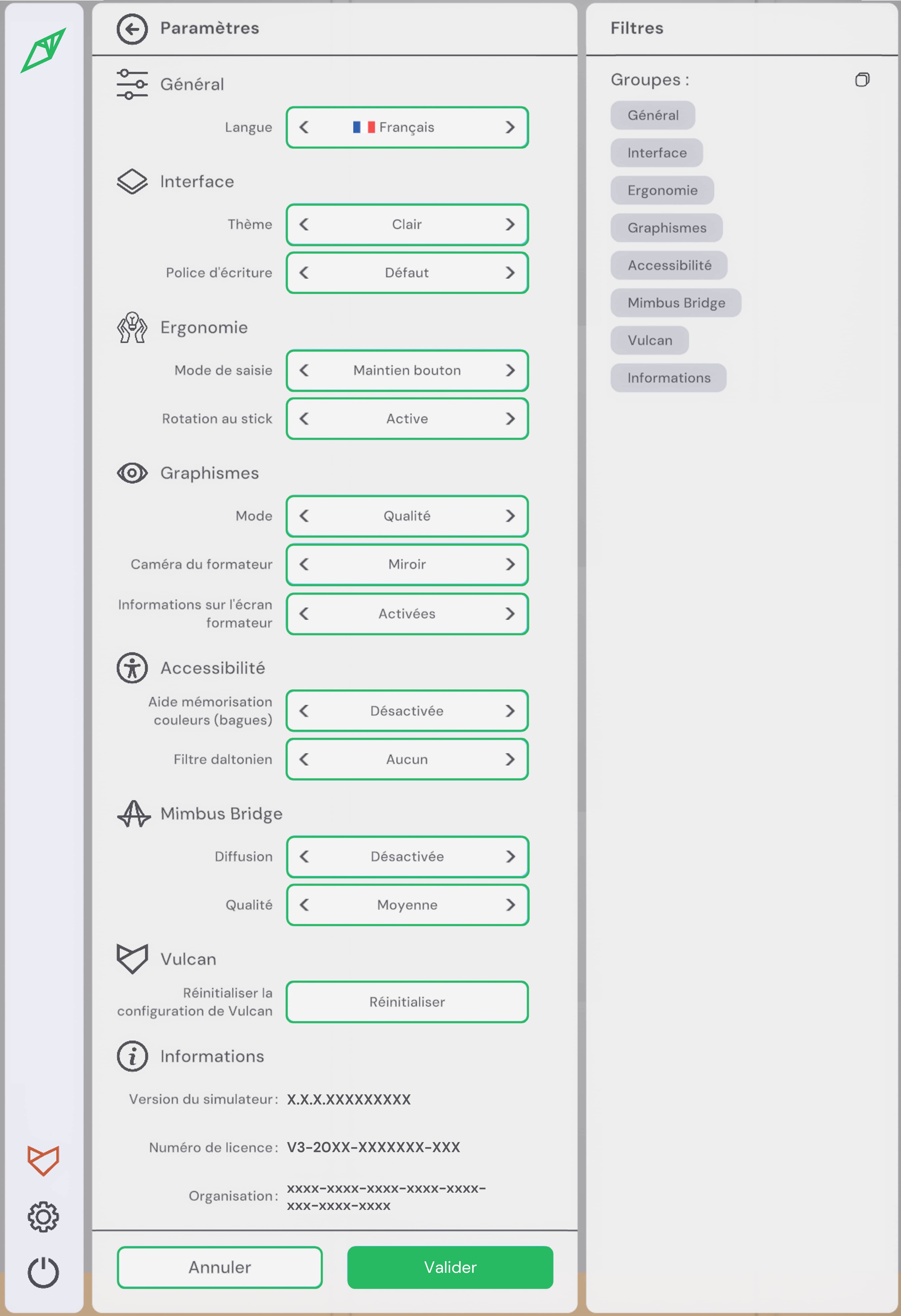
This interface allows you to change the language, adapt the interface, ergonomics, and accessibility according to your preferences, and ensure proper consideration of disabilities (colorblind filter, font adapted for dyslexic people, etc.). It is also possible to adapt the graphics. The Mimbus Bridge section allows you to enable or disable streaming via the MIMBUS BRIDGE application and adjust its quality if necessary. Finally, you will find information about the software version, your license number, and your organization identifier as referenced in the VULCAN LMS. This information may be requested when submitting a support request.
2.2. Controllers
2.2.1. Controllers
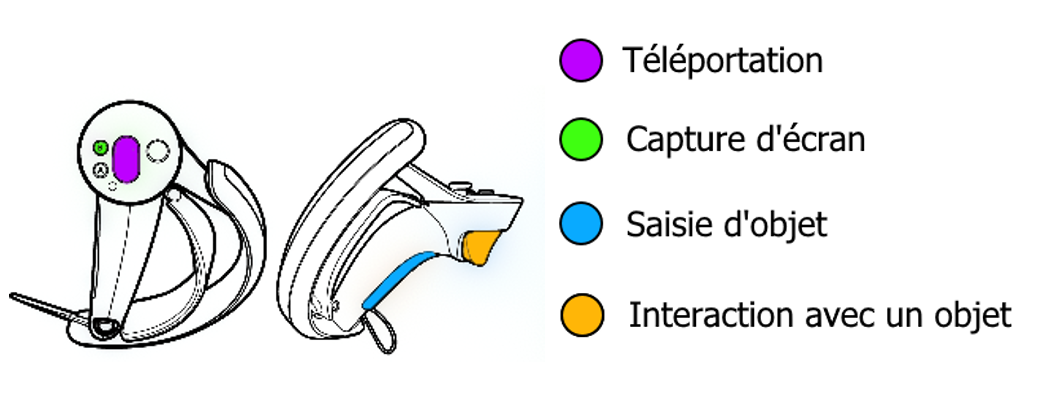
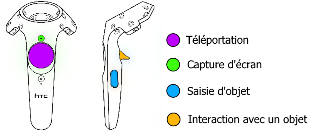
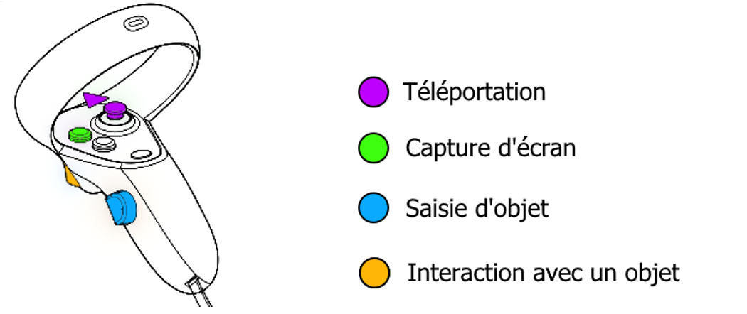
The application is compatible with all headsets supporting the OpenXR standard. Depending on the virtual reality headset used, the controllers and associated buttons differ.
Windows Mixed Reality
Valve Index
HTC Vive
Oculus Rift
3. Tutorial Module
3.1. Tutorial
In order to familiarize the user with the available interactions, a tutorial scenario can be launched from the module selection menu.
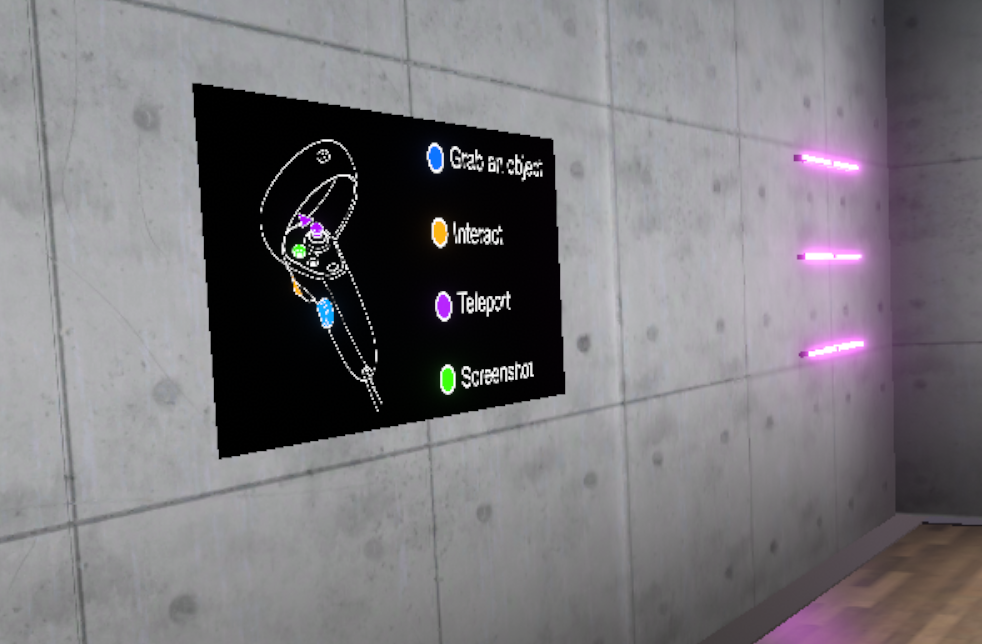
The aim of the tutorial is to teach the user the commands of the virtual reality equipment and the different metaphors used in the application in a clear and progressive way. It will take place in a neutral and uncluttered environment so as not to distract the user from the various actions expected.
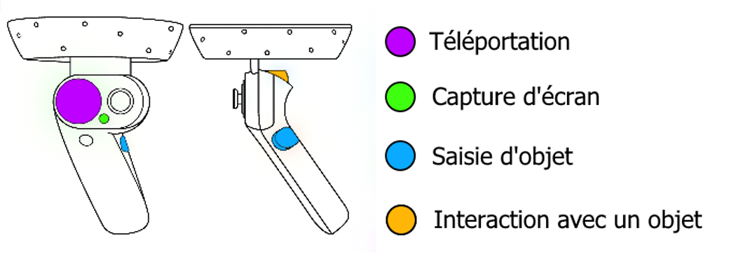
A panel detailing the association between the user’s controllers and the actions will always be visible during the experience.
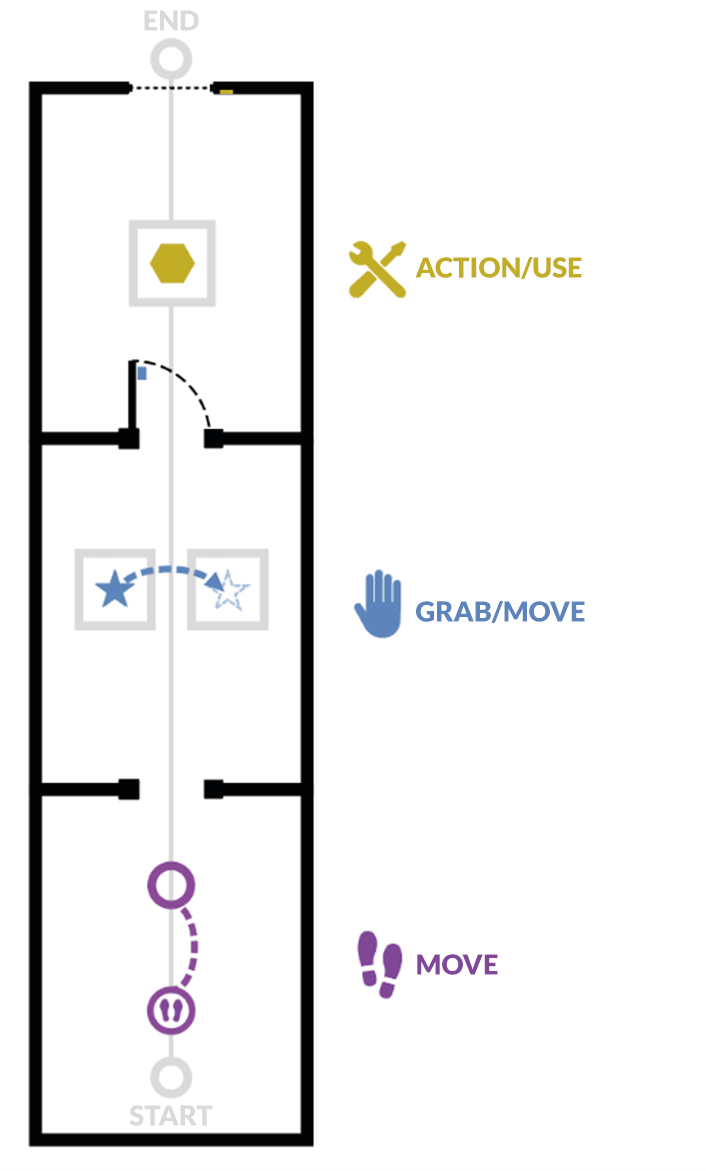
The tutorial is presented in the form of successive themed rooms, which the user will have to perform one after the other:
-
Moving around
-
Grabbing and moving an object
-
Interacting with an object
In each of the rooms, the user will learn an action (i.e., use of a button) in a dedicated space, and then will have to put this action into practice to leave the room and move on to the next. Once the three rooms are completed, the user will go through a final door to finish the tutorial.
3.1.1. Moving
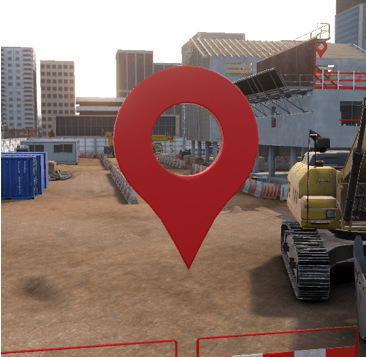
Objective: to learn how to move around the virtual world and recognize markers that indicate a specific location.
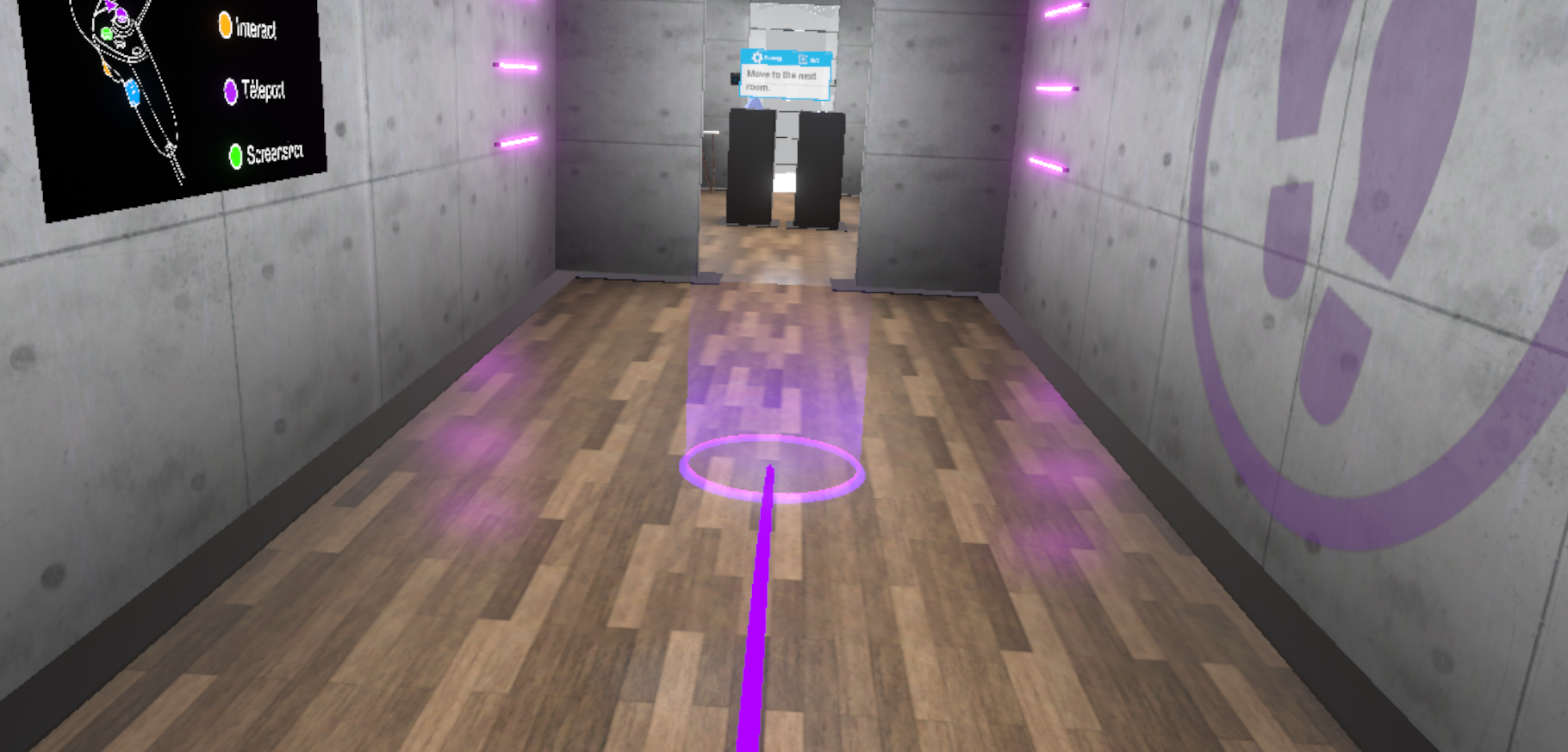
The user will learn to move by teleportation. To leave this first room, the user will be asked to teleport to the next room.
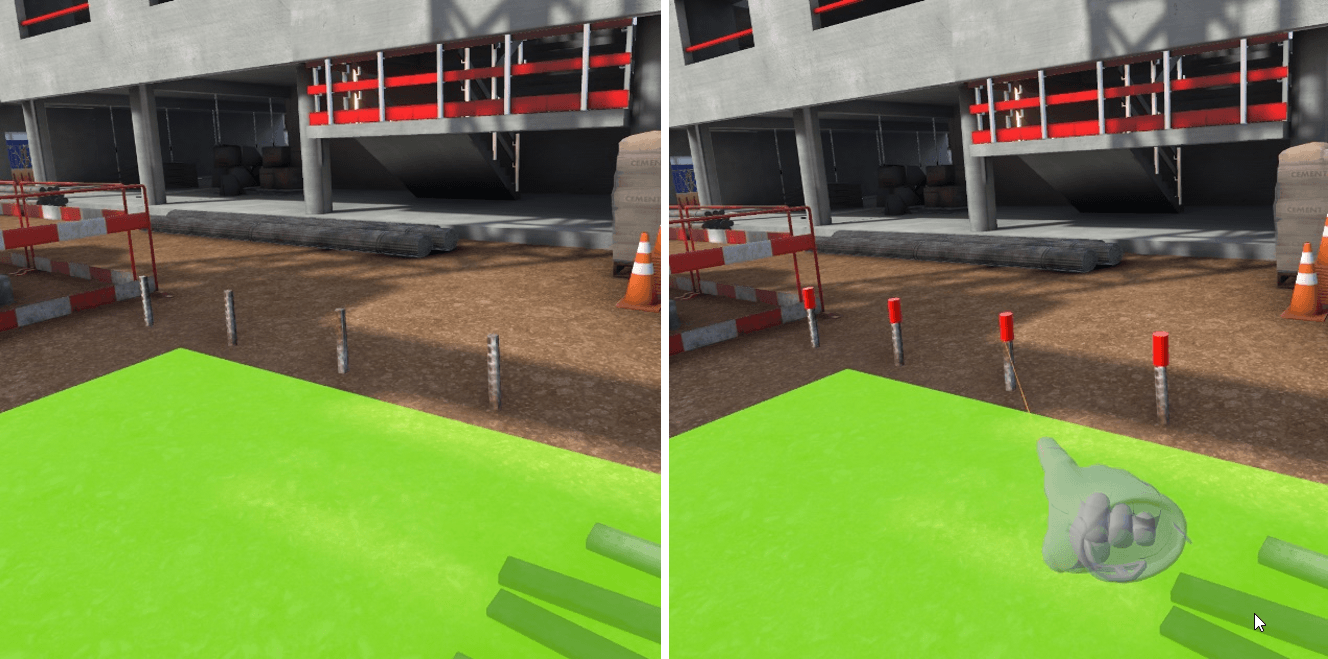
By pressing the "Teleportation" button, it is possible to initiate a teleportation. As long as the button is held down, you can choose the teleportation destination. When you release the button, the teleportation will be performed.
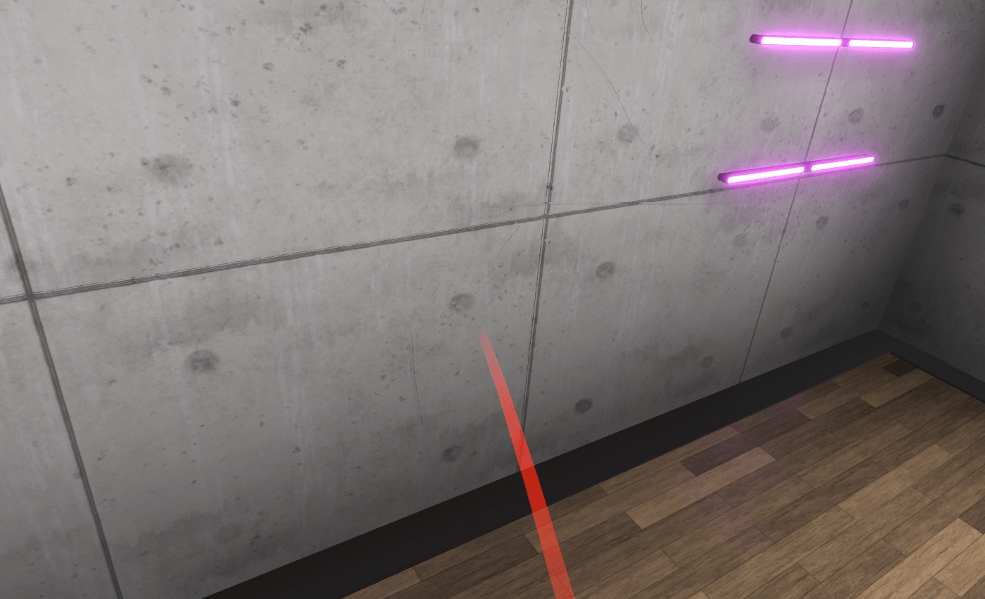
A parabolic pointer coming out of the controller will then be visible, symbolizing the path taken during a teleportation. If teleportation is possible, this pointer is violet; if not, it is red.
3.1.2. Picking Up/Moving an Object
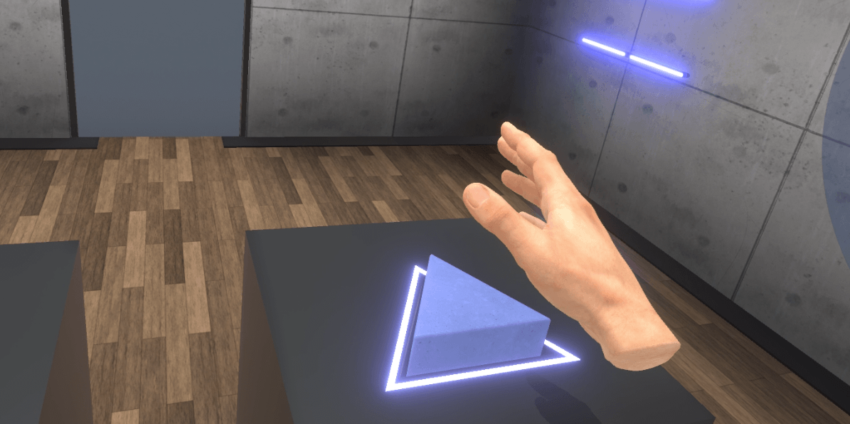
Objective: To learn to pick up an object, release it and place it on a magnetized area, and to recognize the associated visual feedback.
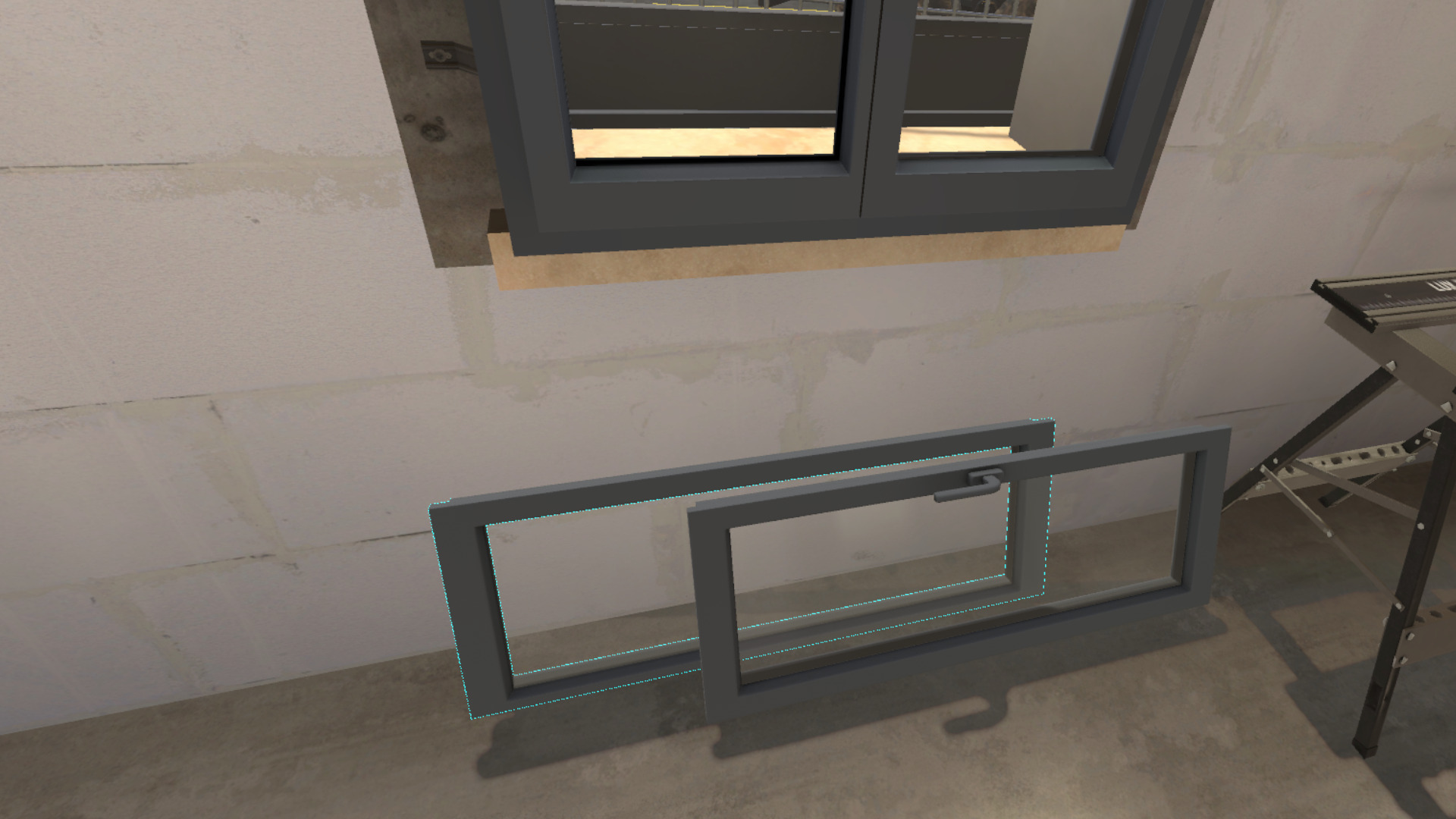
The user will be invited to bring their hand close to an object, visualize the associated visual feedback (blue outline), then pick up the object using the associated button and drop it onto a designated area on a second display.
Once this action is completed, the user will be prompted to exit the room by opening a door, giving them the opportunity to use the "Grab an item" interaction again on the handle.
3.1.3. Action/Using a Tool
Objective: To learn how to interact with tools or buttons, and recognize the associated visual feedback.
The user will be asked to interact with an object on a display (the object will be surrounded by a yellow outline indicating the possibility of activating it) and activate it using the associated button.
To exit the tutorial, the user will have to move to the back of the room and press the elevator button using the "Interact" button. A fade to black will return the user to the lobby.

4. Discovery Module
4.1. Carpentry
Immersed in a construction environment, the user will be required to install a window.
4.1.1. Exercise Plan
-
Check the briefing.
-
Talk to the site manager.
-
Equip themselves with the appropriate PPE for the task.
-
Go out on the site.
-
Talk to the team leader.
-
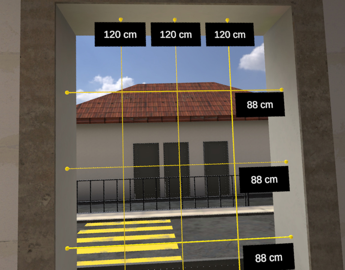
Check the dimensions of the window using the tape measure.
-
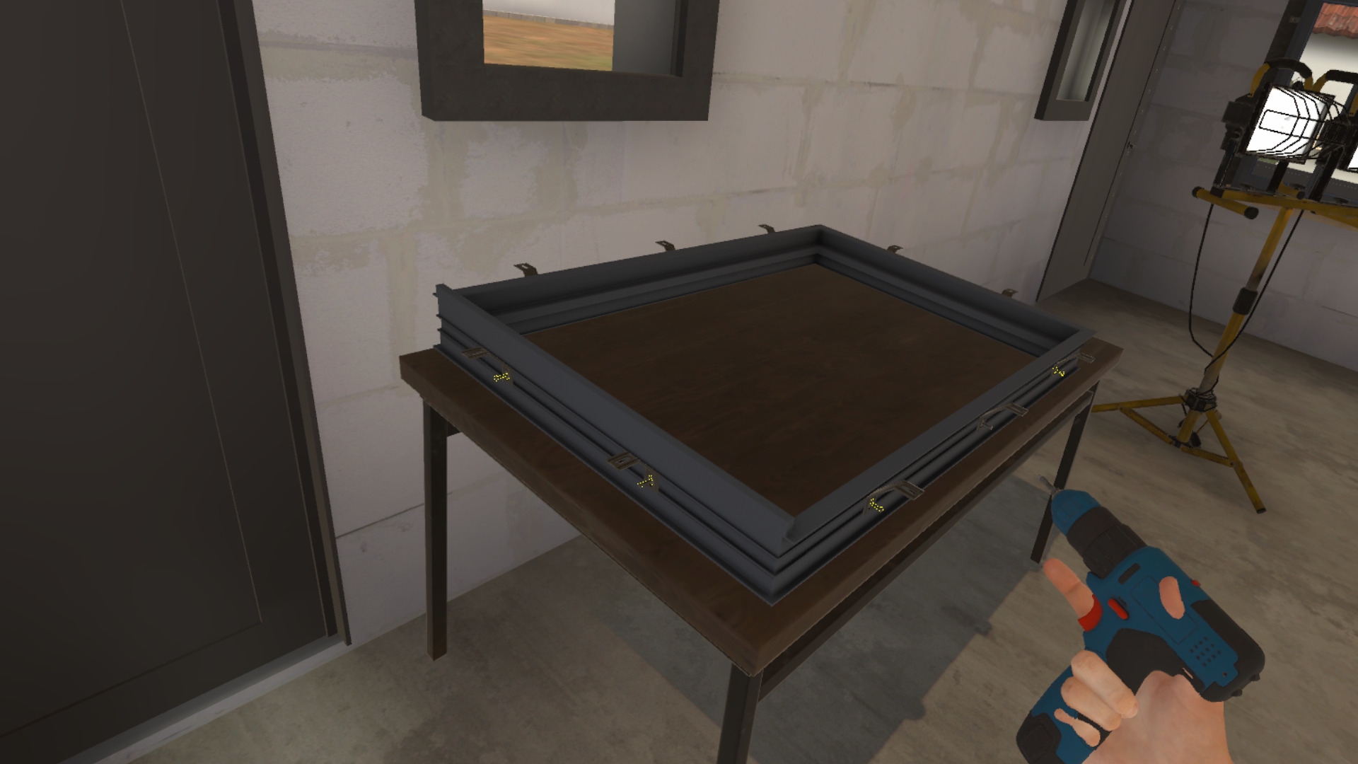
Screw 3 fixing brackets using the screwdriver.
-
Place a pre-compressed seal on the upper part and the sides of the window frame.
-
Place a seal on the windowsill.
-
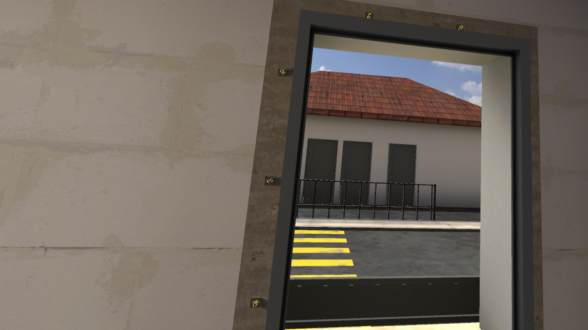
Place the frame in the window opening.
-
Place the spirit levels on the frame to check the verticality and horizontality of the frame.
-
Check the rotation of the frame.
-
Screw 3 pre-installed fixing brackets onto the wall.
-
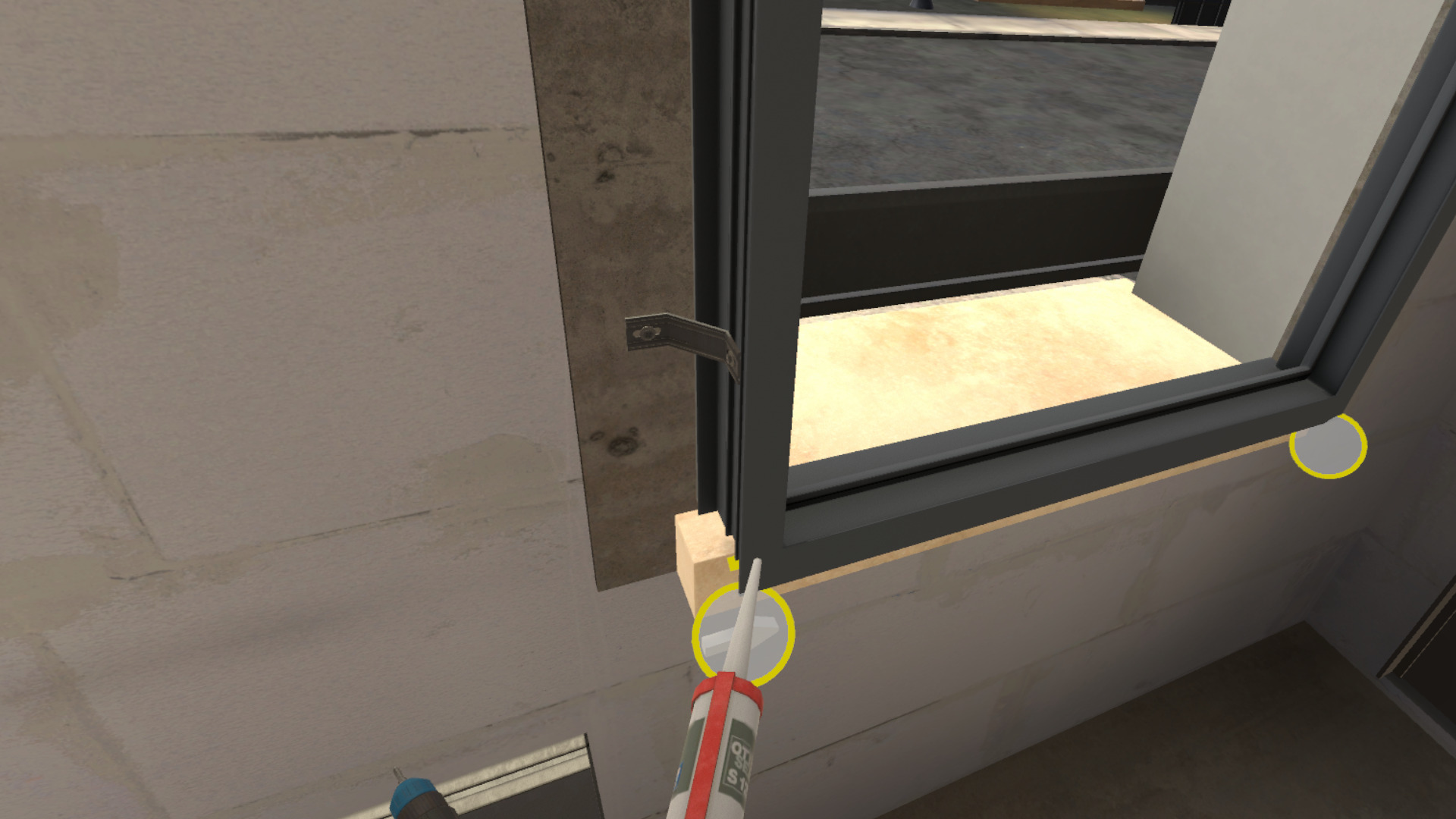
Apply a line of silicone on the base part of the masonry along the joint using the silicone gun.
-
Grab and fit the two sashes onto the frame.
-
Report to your team leader.
4.1.2. Scenario Progress
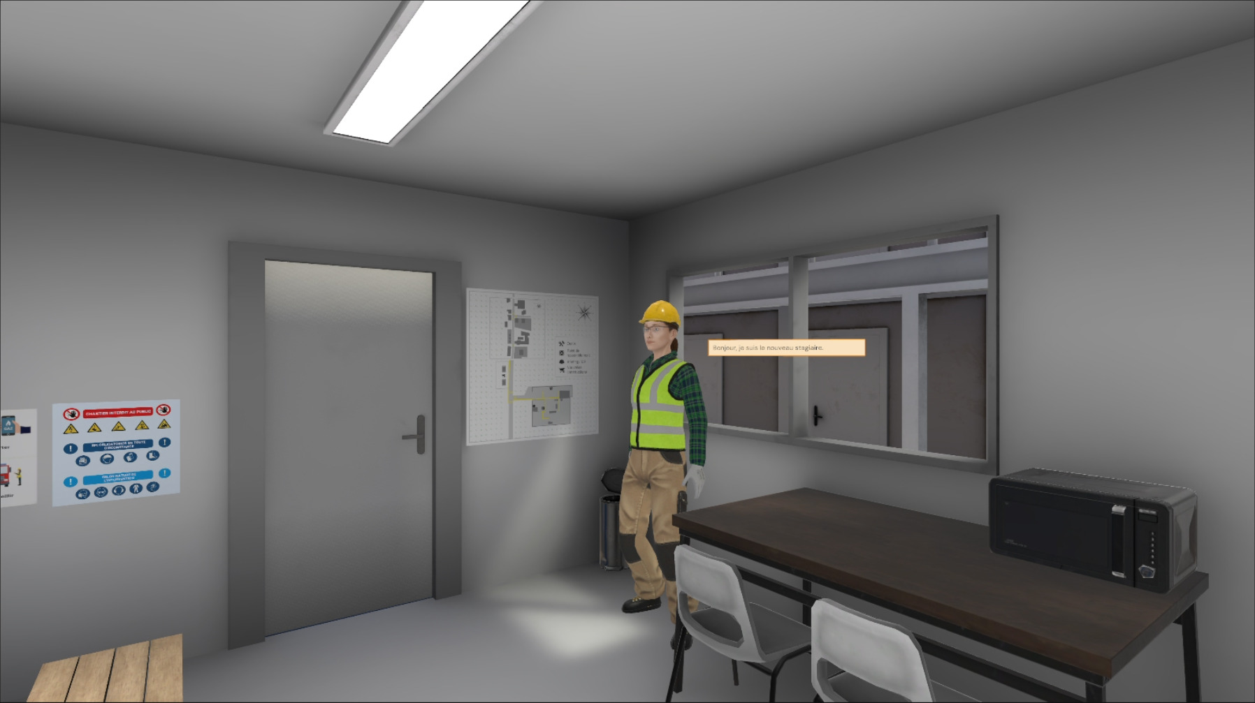
The user begins the scenario inside a portable cabin, facing a briefing screen presenting the context of the mission.
Once the briefing is viewed (or skipped), the site manager stands in a corner of the portable cabin. The user must interact with her to obtain the following information:
-
the task to be performed
-
the mandatory personal protective equipment (PPE) for the intervention
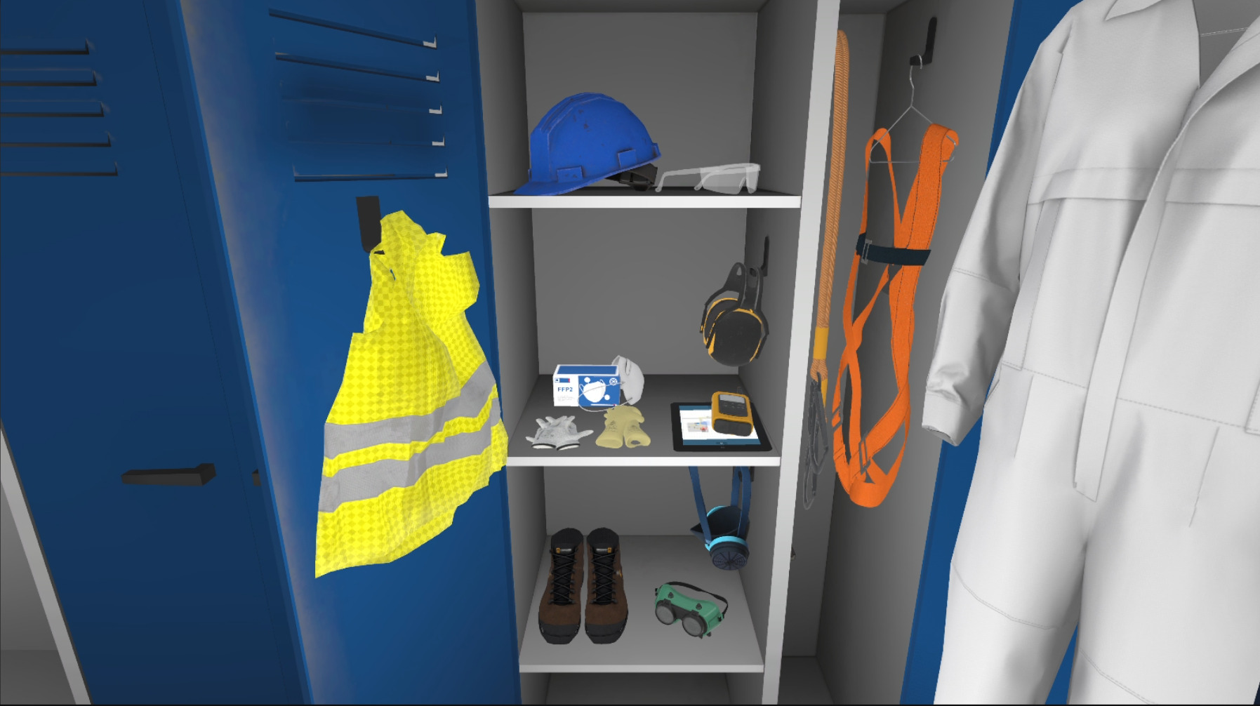
A cabinet containing all the available PPE is also present in the base camp. It will be necessary to choose gloves, a hard hat, a high-visibility vest, safety shoes, earmuffs and a mask before leaving the area.
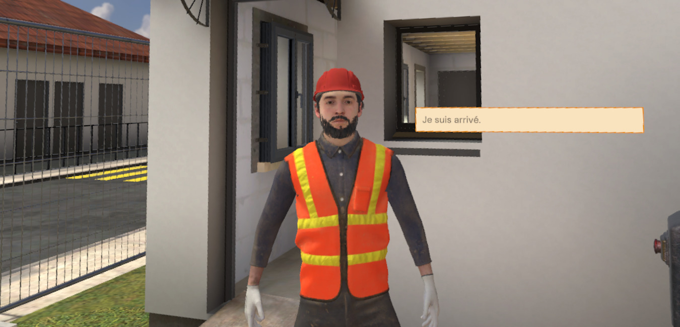
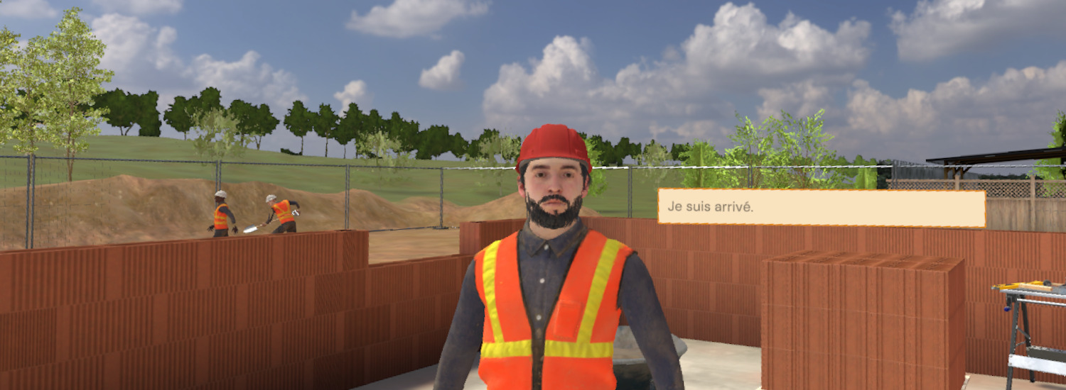
Arriving on the site, the team leader will indicate the concrete task to be performed.
After being teleported into the house, the user will start their work.
First, it will be necessary to take the measurements of the window using the tape measure.
Once the measurements have been taken, screw 3 fixing brackets onto the frame. The other fixing brackets will be automatically screwed.
Take a pre-compressed seal from the trestle and place it on the upper part and the sides of the frame.
Do the same for the seal on the windowsill.


Place the frame in the window opening.
Placing 2 spirit levels on the frame, check its verticality and horizontality. With this, correct the rotation of the frame.


Once correctly positioned, screw 3 pre-installed fixing brackets onto the wall. The other fixing brackets will be automatically screwed.
Using the silicone gun, make a line of silicone on the base part of the masonry along the joint.
Retrieve the sashes from the floor and fit them onto the frame.
When the window is installed, the user will have to report to their team leader.
The exercise is finished once the report is made.
4.1.3. Exercise Evaluation Criteria
![]() Choice of PPE: Evaluates the choice of PPE selected by the user.
Choice of PPE: Evaluates the choice of PPE selected by the user.
![]() Procedure: Validates compliance with the procedure.
Procedure: Validates compliance with the procedure.
4.2. Masonry
Immersed in a construction environment, the user will be led to participate in the realization of a wall from the application of the glue to the correct alignment of the row of blocks.
4.2.1. Exercise Plan
To validate the exercise, the user will have to proceed with the following actions:
-
Check the briefing.
-
Talk to the site manager.
-
Equip themselves with the appropriate PPE for the task.
-
Go out on the site.
-
Talk to the team leader.
-
Take the glue applicator roller.
-
Position the roller at a 25-degree angle on the highlighted row of blocks.
-
Maintain the angle of the roller while moving it along the row.
-
Place the suitable block at the end of the row next to the door opening.
-
Use the spirit level and the mallet to align the block.
-
Place the suitable block at the beginning of the row.
-
Use the spirit level and the mallet to align the block.
-
Place the mason’s line above one of the two previously placed blocks.
-
Finish filling the row by alternating the placement of blocks on each side, making sure to level them.
-
Talk to the team leader.
4.2.2. Scenario Progress
The user begins the scenario inside a portable cabin, facing a briefing screen presenting the context of the mission.
Once the briefing is viewed (or skipped), the site manager stands in a corner of the portable cabin. The user must interact with her to obtain the following information:
-
the task to be performed
-
the mandatory personal protective equipment (PPE) for the intervention
A cabinet containing all the available PPE is also present in the base camp. It will be necessary to choose gloves, a hard hat, a high-visibility vest and safety shoes before leaving the area.
Arriving on the site, their team leader will indicate the concrete task to be performed.
First, apply the glue using the applicator roller. To do this, take the roller and use it on the upper part of the wall. It will be necessary to cover the entire area with glue to move on to the next step.
|
Important
|
The applicator roller must be placed at 25 (+/-5) degrees relative to the wall.
|

When all the glue is applied, take a short brick with a recess. Place it on the side of the opening.
This should not be aligned with the ground, take the mallet as well as the spirit level to check and correct this alignment.


Repeat this manipulation with a standard brick on the other side of the row.
Place the mason’s line on one of the two bricks previously positioned.

Now continue the placement of the other bricks to finalize the wall.
|
Note
|
The bricks must be laid in alternation one after the other.
|

When the wall is built, talk to the team leader to finish the exercise.
4.2.3. Exercise Evaluation Criteria
![]() Choice of PPE: Evaluates the choice of PPE selected by the user.
Choice of PPE: Evaluates the choice of PPE selected by the user.
![]() Procedure: Validates compliance with the procedure.
Procedure: Validates compliance with the procedure.
![]() Execution quality: Evaluates the quality of task execution.
Execution quality: Evaluates the quality of task execution.
5. Electrotechnology Module
5.1. Electrotechnology: Garden Lamp
5.1.1. Exercise Plan
-
Talk to the manager.
-
Talk to the customer.
-
Equip themselves with PPE and take the appropriate equipment for the task from the van.
-
Lock out the luminaire contactor in the LV Main Switchboard room.
-
Replace the luminaire bulb.
-
Turn the lighting back on in the LV Main Switchboard room.
-
Put away the equipment and report the end of the intervention to the customer.
-
Talk to the partner.
-
Fill out the self-check sheet.
5.1.2. Scenario Progress
The user begins the scenario next to a van with a bucket, in the parking lot of a pharmacy. They are close to a Low Voltage Main Switchboard (LVMS) room and facing their manager.

The user must first become aware of the task to be performed by speaking to their superior. A breakdown affects a luminaire near the LVMS and the user will have to replace its bulb safely.
The user must go talk to the customer to obtain more information, they can in particular ask them for the luminaire documentation which specifies the type of bulb to replace, here an E27 bulb.

A cabinet containing all the available PPE is present in the van. To enter, simply touch the side sliding door and press the interaction trigger. It will be necessary to equip the PPE by touching them and then pressing the interaction trigger:
-
Insulated gloves
-
Hard hat (then lower the visor)
-
High-visibility vest

An inventory can be opened by pressing the X or A buttons on the left or right controllers respectively. Objects can be dropped onto the bubbles that appear and then retrieved from these same bubbles. It will be necessary to store in the inventory:
-
The insulating mat
-
Insulated screwdriver
-
Voltage detector (VD)
-
Circuit breaker lockout
-
Lockout padlock
-
LED E27 replacement bulb

The user must go to the LVMS room, an electrical panel is opposite the door while the technical documentation of the LVMS can be consulted on the right. It is specified in the documentation that the Q34 contactor controls the power supply to the exterior parking lot luminaires. It will therefore be necessary to turn it off and lock it out.

First of all, the insulating mat must be placed on the floor in front of the cabinet.

The user can then open the cabinet door and turn off the Q34 contactor. Once turned off, grasp the circuit breaker lockout from the inventory and place it on the Q34 contactor. The lockout padlock can then be placed on the lockout to block interaction with it.

It will now be necessary to grasp the insulated screwdriver to unscrew the faceplate in front of the contactors. This will provide access to the terminals to check the correct power-off.

Once the faceplate is unscrewed and removed from the front, it can be placed on the ground.
You must now grab the VD and test for the absence of voltage at the contactor output. To do this, you must start with a VD self-test to verify its proper functioning. This involves touching the two tips together and confirming with the LEDs and a sound that the device is functioning correctly.

It is then necessary to place the VD tips on different terminals in pairs to check for the presence of current:
-
Input phase (top right of the contactor) and earth: Voltage is present
-
Input neutral (top left of the contactor) and earth: No voltage
-
Output neutral (bottom left of the contactor) and earth: No voltage
-
Output phase (bottom right of the contactor) and earth: No voltage

This demonstrates the absence of current at the contactor output. You must now perform another self-test of the device to confirm that it is still working and thus validate the latest absence of voltage measurement.
The user must now replace the faceplate, screw the two screws at its ends, and then close the LVMS door.

The user must go out and lift the upper cover of the luminaire to remove the bulb. They can store it in their inventory, place the new LED E27 bulb in the place of the old defective bulb, and then replace the cover.

They must then return to the LVMS room, remove the lockout padlock and the circuit breaker lockout and rearm the latter to turn the parking lot lighting back on before closing the door.
Once this is done, they can remove the insulating mat and put it back in their inventory.
The customer must be notified of the end of the intervention, after which it is necessary to go back to the manager and ask for the self-check sheet.


Filling it out ends the exercise.
5.1.3. Exercise Evaluation Criteria
![]() Safety: Evaluates compliance with safety rules and the procedure for verifying the absence of voltage.
Safety: Evaluates compliance with safety rules and the procedure for verifying the absence of voltage.
![]() Execution quality: Evaluates the quality of task execution.
Execution quality: Evaluates the quality of task execution.
![]() Choice of PPE: Evaluates the choice of PPE.
Choice of PPE: Evaluates the choice of PPE.
![]() Communication: Evaluates good communication with the manager and the customer.
Communication: Evaluates good communication with the manager and the customer.
5.2. Electrotechnology: Pharmacy Cross
5.2.1. Exercise Plan
-
Talk to the manager.
-
Talk to the customer.
-
Equip themselves with PPE and take the appropriate equipment for the task from the van.
-
Lock out the cross contactor in the LV Main Switchboard room.
-
Replace the cross.
-
Turn the new cross on in the LV Main Switchboard room.
-
Put away the equipment and report the end of the intervention to the customer.
-
Talk to the partner.
-
Fill out the self-check sheet.
5.2.2. Scenario Progress
The user begins the scenario next to a van with a bucket, in the parking lot of a pharmacy. They are close to a Low Voltage Main Switchboard (LVMS) room and facing their manager.

The user must first become aware of the task to be performed by speaking to their superior. A breakdown affects the lighting of a pharmacy cross and the user will have to replace it safely.
The user must go talk to the customer to obtain more information, they can in particular ask them for the illuminated sign documentation which details the replacement procedure.

A cabinet containing all the available PPE is present in the van. To enter, simply touch the side sliding door and press the interaction trigger. It will be necessary to equip the PPE by touching them and then pressing the interaction trigger:
-
Insulated gloves
-
Hard hat (then lower the visor)
-
High-visibility vest
-
Harness

An inventory can be opened by pressing the X or A buttons on the left or right controllers respectively. Objects can be dropped onto the bubbles that appear and then retrieved from these same bubbles. It will be necessary to store in the inventory:
-
The insulating mat
-
Insulated screwdriver
-
Voltage detector (VD)
-
Circuit breaker lockout
-
Lockout padlock
-
Replacement green cross illuminated sign

The user must go to the LVMS room, an electrical panel is opposite the door while the technical documentation of the LVMS can be consulted on the right. It is specified in the documentation that the Q33 contactor controls the power supply to the illuminated cross. It will therefore be necessary to turn it off and lock it out.
First of all, the insulating mat must be placed on the floor in front of the cabinet.
The user can then open the cabinet door and turn off the Q33 contactor. Once turned off, grasp the circuit breaker lockout from the inventory and place it on the Q33 contactor. The lockout padlock can then be placed on the lockout to block interaction with it.

It will now be necessary to grasp the insulated screwdriver to unscrew the faceplate in front of the contactors. This will provide access to the terminals to check the correct power-off.

Once the faceplate is unscrewed and removed from the front, it can be placed on the ground.
You must now grab the VD and test for the absence of voltage at the contactor output. To do this, you must start with a VD self-test to verify its proper functioning. This involves touching the two tips together and confirming with the LEDs and a sound that the device is functioning correctly.
It is then necessary to place the VD tips on different terminals in pairs to check for the presence of current:
-
Input phase (top right of the contactor) and earth: Voltage is present
-
Input neutral (top left of the contactor) and earth: No voltage
-
Output neutral (bottom left of the contactor) and earth: No voltage
-
Output phase (bottom right of the contactor) and earth: No voltage
This demonstrates the absence of current at the contactor output. You must now perform another self-test of the device to confirm that it is still working and thus validate the latest absence of voltage measurement.
The user must now replace the faceplate, screw the two screws at its ends, and then close the LVMS door.

To reach the illuminated sign, the user will have to use the van’s bucket.

Once on board, pressing the left joystick allows moving up or down. The emergency stop button on the right allows skipping the animation for those prone to motion sickness.

They must first unplug the sign, then unscrew the two screws holding it to the facade.


The cross can then be removed, placed in the inventory and replaced by the new one stored in the inventory.

They must then lower the bucket using the joystick and return to the LVMS room. The lockout padlock and circuit breaker lockout can be removed and the latter must be rearmed to turn the sign lighting back on before closing the door.
Once this is done, the insulating mat can be removed and put back in your inventory.
The customer must be notified of the end of the intervention, after which it is necessary to go back to the manager and ask for the self-check sheet.
Filling it out ends the exercise.
5.2.3. Exercise Evaluation Criteria
![]() Safety: Evaluates compliance with safety rules and the procedure for verifying the absence of voltage.
Safety: Evaluates compliance with safety rules and the procedure for verifying the absence of voltage.
![]() Execution quality: Evaluates the quality of task execution.
Execution quality: Evaluates the quality of task execution.
![]() Choice of PPE: Evaluates the choice of PPE.
Choice of PPE: Evaluates the choice of PPE.
![]() Communication: Evaluates good communication with the manager and the customer.
Communication: Evaluates good communication with the manager and the customer.
5.3. Electrotechnology: Projector
5.3.1. Exercise Plan
-
Talk to the manager.
-
Talk to the customer.
-
Equip themselves with PPE and take the appropriate equipment for the task from the van.
-
Lock out the projector contactor in the LV Main Switchboard room.
-
Replace the defective projector bulb.
-
Turn the projectors back on in the LV Main Switchboard room.
-
Put away the equipment and report the end of the intervention to the customer.
-
Talk to the partner.
-
Fill out the self-check sheet.
5.3.2. Scenario Progress
The user begins the scenario next to a van with a bucket, in the parking lot of a pharmacy. They are close to a Low Voltage Main Switchboard (LVMS) room and facing their manager.

The user must first become aware of the task to be performed by speaking to their superior. A breakdown affects a high projector on the facade of the pharmacy and the user will have to replace a bulb safely.
The user must go talk to the customer to obtain more information, they can ask them for the projector documentation which allows in particular to know the type of bulb to use.

A cabinet containing all the available PPE is present in the van. To enter, simply touch the side sliding door and press the interaction trigger. It will be necessary to equip the PPE by touching them and then pressing the interaction trigger:
-
Insulated gloves
-
Hard hat (then lower the visor)
-
High-visibility vest
-
Harness

An inventory can be opened by pressing the X or A buttons on the left or right controllers respectively. Objects can be dropped onto the bubbles that appear and then retrieved from these same bubbles. For ecological reasons, it will be necessary to replace the defective halogen R7s bulb with a LED R7s bulb. It will be necessary to store in the inventory:
-
The insulating mat
-
Insulated screwdriver
-
Voltage detector (VD)
-
Circuit breaker lockout
-
Lockout padlock
-
LED R7s Bulb

The weather is very windy and makes the intervention at height with the bucket dangerous. The user will have to report this risk to their manager by first announcing they have a problem, which will result in its reduction. If the user does not report this danger, climbing on the bucket will result in a fall and a fatal outcome to the exercise.

The user must go to the LVMS room, an electrical panel is opposite the door while the technical documentation of the LVMS can be consulted on the right. It is specified in the documentation that the Q43 contactor controls the power supply to the facade lighting. It will therefore be necessary to turn it off and lock it out.
First of all, the insulating mat must be placed on the floor in front of the cabinet.
The user can then open the cabinet door and turn off the Q43 contactor. Once turned off, grasp the circuit breaker lockout from the inventory and place it on the Q43 contactor. The lockout padlock can then be placed on the lockout to block interaction with it.

It will now be necessary to grasp the insulated screwdriver to unscrew the faceplate in front of the contactors. This will provide access to the terminals to check the correct power-off.

Once the faceplate is unscrewed and removed from the front, it can be placed on the ground.
You must now grab the VD and test for the absence of voltage at the contactor output. To do this, you must start with a VD self-test to verify its proper functioning. This involves touching the two tips together and confirming with the LEDs and a sound that the device is functioning correctly.
It is then necessary to place the VD tips on different terminals in pairs to check for the presence of current:
-
Input phase (top right of the contactor) and earth: Voltage is present
-
Input neutral (top left of the contactor) and earth: No voltage
-
Output neutral (bottom left of the contactor) and earth: No voltage
-
Output phase (bottom right of the contactor) and earth: No voltage
This demonstrates the absence of current at the contactor output. You must now perform another self-test of the device to confirm that it is still working and thus validate the latest absence of voltage measurement.
The user must now replace the faceplate, screw the two screws at its ends, and then close the LVMS door.
To reach the projector, the user will have to use the van’s bucket.
Once on board, pressing the left joystick allows moving up or down. The emergency stop button on the right allows skipping the animation for those prone to motion sickness.
You must first unscrew the screw that holds the projector housing and then click on it to open it.

It is then necessary to check the correct power-off of the projector using the VD. As before, you must first perform a self-test, check the voltage between the two ends of the bulb, and then perform another self-test.
|
|


The defective halogen R7s bulb can then be removed and replaced with the new LED R7s bulb.

All that remains is to close and screw back the housing.

They must then lower the bucket using the joystick and return to the LVMS room. The lockout padlock and circuit breaker lockout can be removed and the latter must be rearmed to turn the facade lighting back on before closing the door.
Once this is done, the insulating mat can be removed and put back in your inventory.
The customer must be notified of the end of the intervention, after which it is necessary to go back to the manager and ask for the self-check sheet.
Filling it out ends the exercise.
5.3.3. Exercise Evaluation Criteria
![]() Safety: Evaluates compliance with safety rules and the procedure for verifying the absence of voltage.
Safety: Evaluates compliance with safety rules and the procedure for verifying the absence of voltage.
![]() Execution quality: Evaluates the quality of task execution.
Execution quality: Evaluates the quality of task execution.
![]() Choice of PPE: Evaluates the choice of PPE.
Choice of PPE: Evaluates the choice of PPE.
![]() Communication: Evaluates good communication with the manager and the customer.
Communication: Evaluates good communication with the manager and the customer.
6. Construction Site Safety Module
6.1. Alert: Property Damage
Immersed in a construction site environment, the user is in the base camp waiting to receive their mission. The user will be required to go to the storage area to check the stocks for the next order, but upon arriving, an incident will occur. Following the 4A rule, the user will have to take charge of the procedure to arrest (Stop) the incident, arrange (Secure) the area, alert of the danger and accommodate (Welcome) their site manager.
6.1.1. Exercise Plan
To validate the entire exercise, the user will have to perform the actions in the following order:
-
Check the briefing.
-
Talk to the site manager.
-
Ask the site manager for safety instructions.
-
Ask the site manager for work instructions.
-
Equip themselves with the appropriate PPE for the task before going out on the site.
-
Leave the base camp.
-
Go to the storage area.
-
Start the 4A procedure.
-
Remove the structures that have just fallen.
-
Call the site manager.
-
Secure the incident area.
-
Welcome the site manager.
6.1.2. Scenario Progress
The user begins the scenario inside the base camp, facing a briefing screen presenting the context of the mission.
Once the briefing is viewed (or skipped), the site manager stands in a corner of the base camp. The user must interact with her to learn about:
-
the task to be performed
-
the mandatory personal protective equipment (PPE) for the intervention
A cabinet containing all the available PPE is also present in the base camp.
It will be necessary to choose gloves, a hard hat, a high-visibility vest and safety shoes before leaving the area.
Once properly equipped, the user leaves the base camp and goes to the storage area.
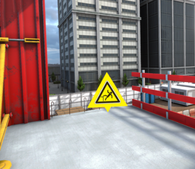
Upon arrival in this area, an incident occurs: metal bars fall from the storage rack, creating a dangerous situation.

Faced with this incident, the user must apply the 4A procedure to secure the situation.

-
Arrest (Stop): Secure the area by removing or stabilizing the unstable metal bars.
-
Alert: Contact the site manager to report the incident.
-
Answers to the MCQ:
-
1. Call the site manager.
-
2. Hello, I am witnessing an incident.
-
3. I am at the industrial wasteland construction site, in the storage area.
-
4. A strap came loose and reinforcement bars fell to the ground.
-
5. No.
-
6. Yes, me.
-
-
-
Arrange (Secure): Set up marking cones to prevent any secondary accidents.

-
Accommodate (Welcome): Wait near the incident area to welcome the site manager upon her arrival.
Once the 4A procedure is correctly carried out, the user is automatically teleported to the lobby, facing the summary screen of their performance.
6.1.3. Exercise Evaluation Criteria
![]() Safety: Evaluates the user’s choice of PPE.
Safety: Evaluates the user’s choice of PPE.
![]() Incident reaction time: Evaluates the execution speed of the 4A procedure following the incident.
Incident reaction time: Evaluates the execution speed of the 4A procedure following the incident.
![]() Arrest (Stop): Evaluates if all elements have been stopped.
Arrest (Stop): Evaluates if all elements have been stopped.
![]() Alert: Evaluates if the user has chosen the right service to contact and if they give them the correct information.
Alert: Evaluates if the user has chosen the right service to contact and if they give them the correct information.
![]() Arrange (Secure): Evaluates the quality of the arrangement of the incident area.
Arrange (Secure): Evaluates the quality of the arrangement of the incident area.
![]() Accommodate (Welcome): Evaluates the quality of the welcome of the service contacted by the user.
Accommodate (Welcome): Evaluates the quality of the welcome of the service contacted by the user.
![]() Procedure: Validates compliance with the order of the 4A procedure.
Procedure: Validates compliance with the order of the 4A procedure.
6.2. Alert: Bodily Injury
Immersed in a home renovation environment, the user is in the base camp waiting for their mission. A briefing is presented by the site manager to explain the tasks to be performed.
During the exercise, a site accident involving bodily injury occurs. The user is then responsible for applying the 4A procedure: arresting (stopping) the tools, arranging (securing) the area, alerting emergency services and accommodating (welcoming) external responders.
6.2.1. Exercise Plan
To validate the entire exercise, the user will have to perform the following actions in the indicated order:
-
Check the briefing.
-
Talk to the site manager.
-
Ask the site manager for safety instructions.
-
Ask the site manager for work instructions.
-
Equip themselves with the appropriate PPE for the task before going out on the site.
-
Leave the base camp.
-
Talk to the team leader.
-
Pick up the rubble.
-
An accident occurs.
-
Start the 4A procedure.
-
Stop the cutter.
-
Remove the block located up high.
-
Bend the iron rod sticking out of the wall.
-
Inform the construction site colleague working in the next room.
-
Ask this colleague to wait outside to welcome the emergency services.
-
Call emergency services.
-
Secure the accident area.
6.2.2. Scenario Progress
The user begins the scenario inside the base camp, facing a briefing screen presenting the context of the mission.
Once the briefing is viewed (or skipped), the site manager stands in a corner of the base camp. The user must interact with her to obtain the following information:
-
the task to be performed
-
the mandatory personal protective equipment (PPE) for the intervention
A cabinet containing all the available PPE is also present in the base camp. It will be necessary to choose gloves, a hard hat, a high-visibility vest, earmuffs and safety shoes before leaving the area.
Once properly equipped, the user leaves the base camp and is teleported to their workplace.
Upon arrival at the area, the team leader tells them the tasks to be carried out in the house.
Entering the building, the user must clear the rubble on the floor.

While depositing the rubble in the wheelbarrow, an accident occurs: the colleague cutting the wall falls, taking the cutter with him.
Faced with this accident, the user must apply the 4A procedure to secure the situation.
-
Arrest (Stop): Secure the area by stopping the cutter and dropping the wall block located above the colleague on the ground.

-
Alert: Go warn the worker in the next room, then contact emergency services.
-
Answer to the walkie-talkie discussion:
-
-
Arrange (Secure): Set up marking cones to prevent any secondary accidents.

-
Accommodate (Welcome): During the exchange with the worker, ask him to wait in front of the building to welcome the emergency services.
-
Answers to the discussion with the colleague:
-
1. Watch out, there’s just been an accident in the back.
-
2. Stop what you’re doing and go welcome the emergency services at the door.
-
-
Once the 4A procedure is correctly carried out, the user is automatically teleported to the lobby, facing a summary screen of their performance.
6.2.3. Exercise Evaluation Criteria
![]() Choice of PPE: Evaluates the choice of PPE selected by the user.
Choice of PPE: Evaluates the choice of PPE selected by the user.
![]() Incident reaction time: Evaluates the execution speed of the 4A procedure following the incident.
Incident reaction time: Evaluates the execution speed of the 4A procedure following the incident.
![]() Arrest (Stop): Evaluates if all dangerous elements have been correctly stopped.
Arrest (Stop): Evaluates if all dangerous elements have been correctly stopped.
![]() Alert: Evaluates if the user has contacted the appropriate service and transmitted the necessary information.
Alert: Evaluates if the user has contacted the appropriate service and transmitted the necessary information.
![]() Arrange (Secure): Evaluates the quality of the arrangement of the incident area.
Arrange (Secure): Evaluates the quality of the arrangement of the incident area.
![]() Accommodate (Welcome): Evaluates the quality of the welcome of emergency services by the user.
Accommodate (Welcome): Evaluates the quality of the welcome of emergency services by the user.
![]() Procedure: Validates compliance with the order and steps of the 4A procedure.
Procedure: Validates compliance with the order and steps of the 4A procedure.
6.3. Safety: Circulation
Immersed in a construction site environment, the user is in the base camp waiting for their mission. They will have to go to a container to retrieve a toolbox, then give it to their team leader.
Throughout the exercise, the user will have to respect safety and circulation rules. They will in particular have to pay attention to the vehicles present in the area and adopt the appropriate behavior in the event of an emergency or accident situation.
|
Note
|
This exercise is divided into three parts, each corresponding to a difficulty level. These parts follow one another, so it is preferable to do them in order. |
6.3.1. Exercise Plan
To validate all the difficulties of the exercise, the user will have to perform the following actions in the indicated order:
Beginner difficulty
-
Check the briefing.
-
Equip themselves with the appropriate PPE for movement on a construction site.
-
Go to the tool container respecting circulation rules.
Advanced difficulty
-
Take the walkie-talkie attached to the belt.
-
Retrieve the toolbox.
-
Hand the toolbox to the team leader.
Expert difficulty
-
Take the walkie-talkie attached to the belt.
-
Return to the base camp.
-
A gas pipe explodes.
-
Go to the assembly point respecting safety instructions.
6.3.2. Scenario Progress
Beginner difficulty
In the beginner level, the user begins the scenario inside the base camp, facing a briefing screen presenting the context of the mission.
Once the briefing is viewed (or skipped), the site manager stands in a corner of the base camp. The user must interact with her to obtain the following information:
-
the task to be performed
-
the mandatory personal protective equipment (PPE) for the intervention
A cabinet containing all the available PPE is also present in the base camp. It will be necessary to choose gloves, a hard hat, a high-visibility vest and safety shoes before leaving the area.
Once properly equipped, the user leaves the base camp and goes to the tool container, making sure to respect the site’s circulation rules. The exercise ends when the user reaches the tool container.

Advanced difficulty
In the advanced level, the user starts directly in the tool container. A walkie-talkie is attached to their belt and presents them with the task to be carried out as well as the associated instructions.

The user must then retrieve the toolbox, then go to the site where the team leader is located. The team leader is identifiable by his red hard hat.

The exercise ends when the user correctly hands the toolbox to the team leader.
Expert difficulty
In the expert level, the user begins the scenario facing the team leader met during the advanced level.
A walkie-talkie is attached to their belt and presents them with the task to be performed.
While retrieving the walkie-talkie, a gas pipe explodes, leading to the immediate shutdown of the site and the triggering of an emergency situation.

The user must then go to the assembly point respecting circulation rules. When passing through smoke-filled areas, they must crouch to limit their exposure to the smoke emitted by the explosion.

Upon arrival at the assembly point, the user must wait for the other workers. The exercise ends when all workers are present and safe.

At the end of each exercise, the user is automatically teleported to the lobby, facing a summary screen of their performance, the actions carried out and any errors made.
6.3.3. Exercise Evaluation Criteria
![]() Safety (Beginner level only): Evaluates the choice of PPE selected by the user.
Safety (Beginner level only): Evaluates the choice of PPE selected by the user.
![]() Use of pedestrian areas: Evaluates the use of areas reserved for pedestrians during the user’s movements.
Use of pedestrian areas: Evaluates the use of areas reserved for pedestrians during the user’s movements.
![]() Compliance with circulation rules: Evaluates compliance with circulation rules.
Compliance with circulation rules: Evaluates compliance with circulation rules.
![]() Use of emergency exits (Expert level only): Evaluates the user’s correct placement in the assembly area.
Use of emergency exits (Expert level only): Evaluates the user’s correct placement in the assembly area.
![]() Compliance with evacuation instructions (Expert level only): Evaluates compliance with evacuation rules.
Compliance with evacuation instructions (Expert level only): Evaluates compliance with evacuation rules.
6.4. Safety: Execute
Immersed in a construction site environment, the user will have to go to the renovation area to carry out safety visual checks.
|
Note
|
This exercise is divided into three parts, each corresponding to a difficulty level. These parts follow one another, so it is preferable to do them in order. |
6.4.1. Exercise Plan
To validate all the difficulties of the exercise, the user will have to perform the following actions in the indicated order:
Beginner difficulty
-
Check the briefing.
-
Talk to the site manager.
-
Equip themselves with the appropriate PPE for the task before going out on the site.
-
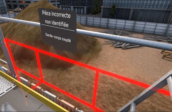
Go to the work area while identifying all encountered dangerous situations using the laser pointer.
Advanced difficulty
-
Identify the 3 defects on the floor.
Expert difficulty
-
Identify the 5 missing pieces of personal protective equipment in the work team.
6.4.2. Scenario Progress
Beginner difficulty
In the beginner level, the user begins the scenario inside the base camp, facing a briefing screen presenting the context of the mission.
Once the briefing is viewed (or skipped), the site manager stands in a corner of the base camp. The user must interact with her to obtain the following information:
-
the task to be performed
-
the mandatory personal protective equipment (PPE) for the intervention
A cabinet containing all the available PPE is also present in the base camp. It will be necessary to choose gloves, a hard hat, a high-visibility vest and safety shoes before leaving the area.
Once properly equipped, the user leaves the base camp and goes to the renovation area, making sure to respect the site’s circulation rules. A laser on the belt helps identify dangerous situations encountered.


The exercise ends when the user reaches the renovation area.
Advanced difficulty
In the advanced level, the user finds themselves on the renovation site.
A walkie-talkie on the belt allows communication with the site manager to receive instructions.
Expert difficulty
In the expert level, the user finds themselves on the renovation site.
A walkie-talkie on the belt allows communication with the site manager to receive instructions.
6.4.3. Exercise Evaluation Criteria
![]() Hazard identification: Validates the choices of identifications.
Hazard identification: Validates the choices of identifications.
![]() Compliance with circulation rules (Beginner level only): Evaluates compliance with circulation rules.
Compliance with circulation rules (Beginner level only): Evaluates compliance with circulation rules.
![]() Choice of CPE (Advanced level only): Evaluates the choice of collective protective equipment selected by the user.
Choice of CPE (Advanced level only): Evaluates the choice of collective protective equipment selected by the user.
![]() Choice of PPE (Beginner and expert levels only): Evaluates the choice of personal protective equipment selected by the user.
Choice of PPE (Beginner and expert levels only): Evaluates the choice of personal protective equipment selected by the user.
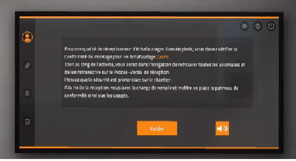
6.5. Evaluation: Prevention
Immersed in a construction site environment, the user will have to go to the renovation area to verify safety points before commissioning a scaffolding. Going up to the top floor, a colleague is working and by informing him an incident occurs. You will have to act accordingly while respecting safety procedures.
6.5.1. Exercise Plan
To validate all the difficulties of the exercise, the user will have to perform the following actions in the indicated order:
-
Check the briefing.
-
Talk to the site manager.
-
Equip themselves with the appropriate PPE for the task.
-
Leave the base camp.
-
Go to the renovation area.
-
Verify all safety points for commissioning the scaffolding.
-
Ask the colleague to stop working.
-
The colleague falls.
-
Take the necessary measures by following the 4A procedure.
6.5.2. Scenario Progress
The user begins the scenario inside the base camp, facing a briefing screen presenting the context of the mission.
Once the briefing is viewed (or skipped), the site manager stands in a corner of the base camp. The user must interact with her to obtain the following information:
-
the task to be performed
-
the mandatory personal protective equipment (PPE) for the intervention
A cabinet containing all the available PPE is also present in the base camp. It will be necessary to choose gloves, a hard hat, a high-visibility vest, safety shoes and a harness before leaving the area.
Once properly equipped, the user leaves the base camp and goes to the renovation area, making sure to respect the site’s circulation rules.

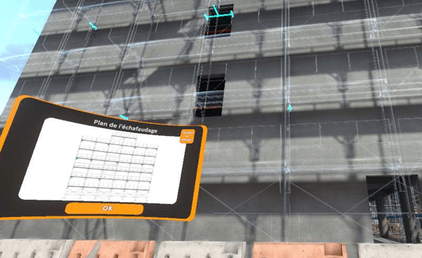
In front of the scaffolding, a safety sheet is present on the tablet on the belt. Using the laser pointer also located on the belt, the user must reference the non-compliant safety points within the scaffolding.


Arriving on the top floor, a colleague is working on this scaffolding even though it has not yet been verified. The user must ask the colleague to stop working. When the user approaches him, the colleague falls. Faced with this accident, the user must apply the 4A procedure to secure the situation.


-
Arrest (Stop): Turn off the drill and put the safety barrier back in place.

-
Alert: Contact emergency services.
-
Answers to the walkie-talkie conversation:
-
1. Call emergency services.
-
2. Hello, there’s just been an accident at my workplace.
-
3. I am on the construction site at 12 rue du bac, in Valenciennes, in the renovation area.
-
4. Yes.
-
5. There is one person.
-
6. Yes, I’m waiting for you outside.
-
-
-
Arrange (Secure): Place marking cones to block access to the scaffolding.

-
Accommodate (Welcome): Go to the side of the road to wait for emergency services. Welcoming also takes into account the correct response to the walkie-talkie conversation.
The exercise ends when the user reaches the side of the road to wait for emergency services.
6.5.3. Exercise Evaluation Criteria
![]() Choice of PPE: Evaluates the choice of PPE selected by the user.
Choice of PPE: Evaluates the choice of PPE selected by the user.
![]() Compliance with circulation rules: Evaluates compliance with circulation rules.
Compliance with circulation rules: Evaluates compliance with circulation rules.
![]() Hazard identification: Validates the choices of identifications.
Hazard identification: Validates the choices of identifications.
![]() Reaction time following an incident: Evaluates the user’s reaction time following an incident.
Reaction time following an incident: Evaluates the user’s reaction time following an incident.
![]() Arrest (Stop): Evaluates if all dangerous elements have been correctly stopped.
Arrest (Stop): Evaluates if all dangerous elements have been correctly stopped.
![]() Alert: Evaluates if the user has contacted the appropriate service and transmitted the necessary information.
Alert: Evaluates if the user has contacted the appropriate service and transmitted the necessary information.
![]() Arrange (Secure): Evaluates the quality of the arrangement of the incident area.
Arrange (Secure): Evaluates the quality of the arrangement of the incident area.
![]() Accommodate (Welcome): Evaluates the quality of the welcome of emergency services by the user.
Accommodate (Welcome): Evaluates the quality of the welcome of emergency services by the user.
![]() Procedure: Validates compliance with the order and steps of the 4A procedure.
Procedure: Validates compliance with the order and steps of the 4A procedure.
7. Construction site safety
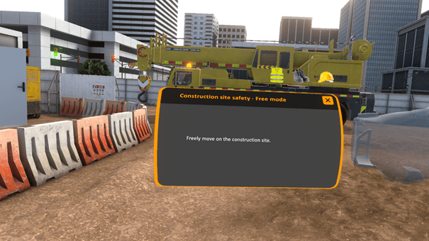
7.1. Free Mode
In free mode, the user can move freely on the construction site. All the possible risks on the construction site are present and fatal errors occur if the user gets too close to one of the risks. The exercise will be validated if the user is able to cover a distance indicated by the trainer in VULCAN in a defined time.
In this mode, the user does not have the possibility of securing the dangers that he encounters, and can leave the exercise at any time by clicking on the cross present on the tablet at his left wrist.
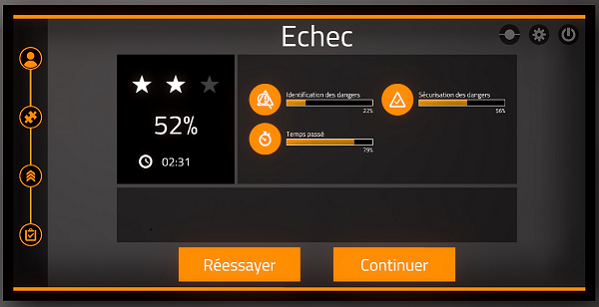
Exercise evaluation criteria
![]() Distance covered by the user
Distance covered by the user
![]() Time before accident
Time before accident
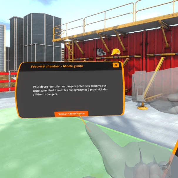
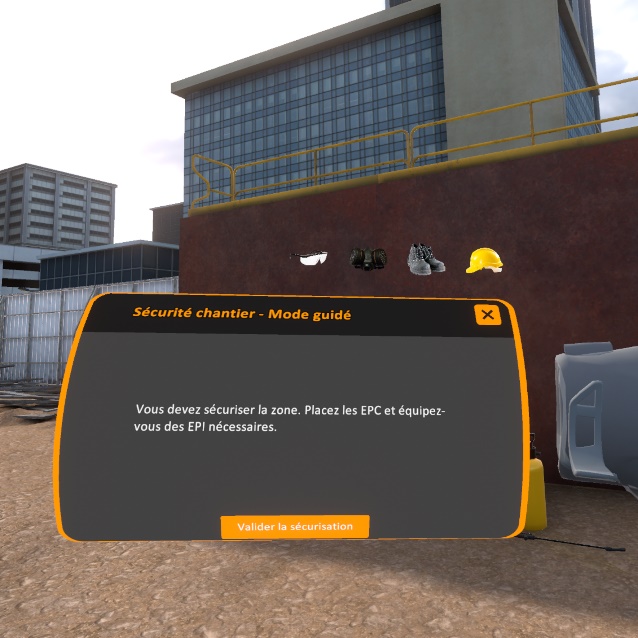
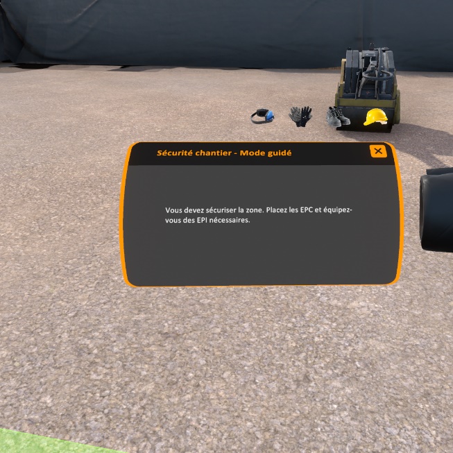
7.2. Guided mode
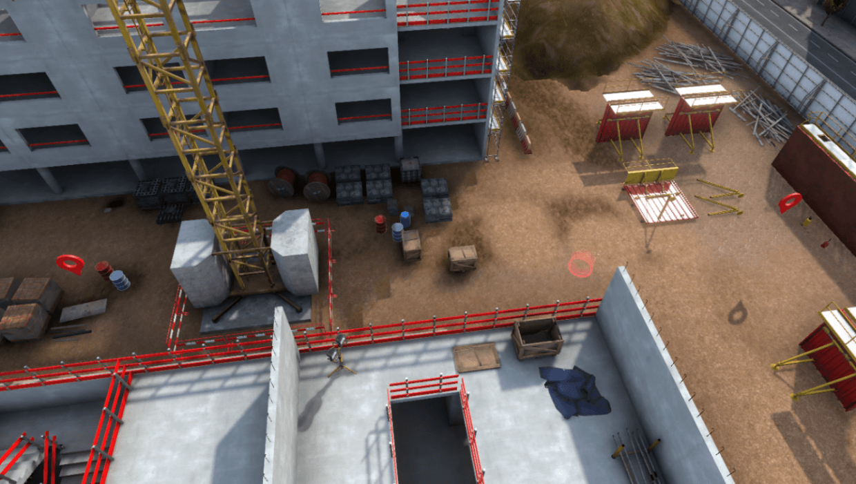
The guided mode takes place on one of the three construction site zones. The user must identify then secure the different dangers present in the zone selected.
Several work stations are present in a zone and are identified by a floating marker above the them.
The user is free to go on the workstations in the zone in the order that he wishes. He need only position himself under a marker to activate the sequence of phases specific to this workstation.
Once he is on a workstation, user movements are limited, he can’t directly deal with dangers in the zone.
Exercise evaluation criteria
![]() Identification : capacity to correctly identify and classify the
dangers.
Identification : capacity to correctly identify and classify the
dangers.
![]() Securing: capacity to correct dangers
Securing: capacity to correct dangers
![]() Completion time : capacity to finish the scenario in a defined time
Completion time : capacity to finish the scenario in a defined time
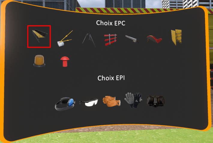
7.2.1. Identification procedure
Once the user is on the workstation, he is asked to identify the different risks present.
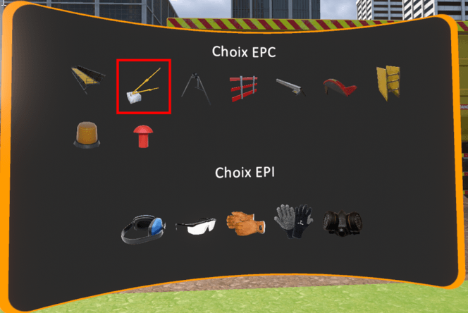
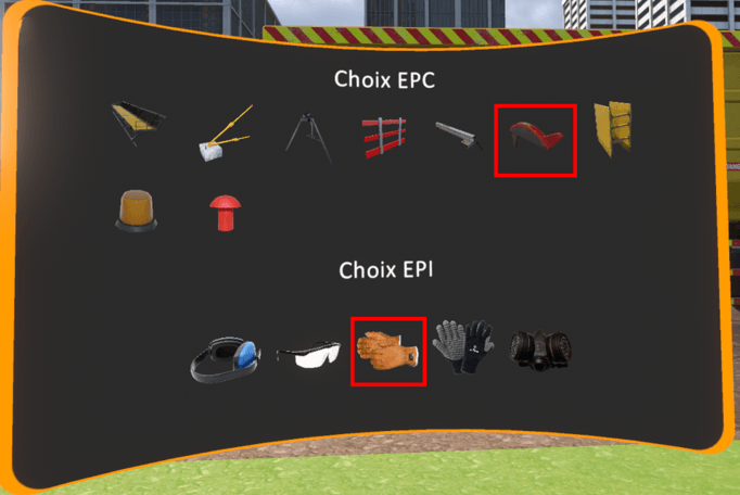
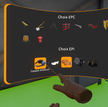
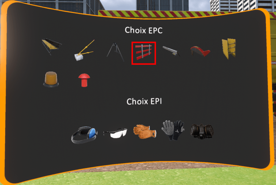
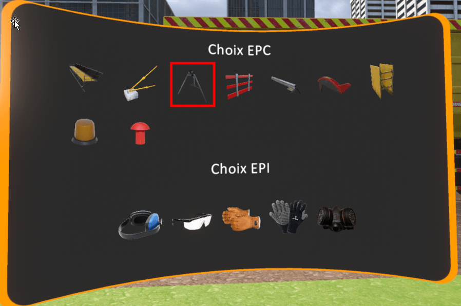
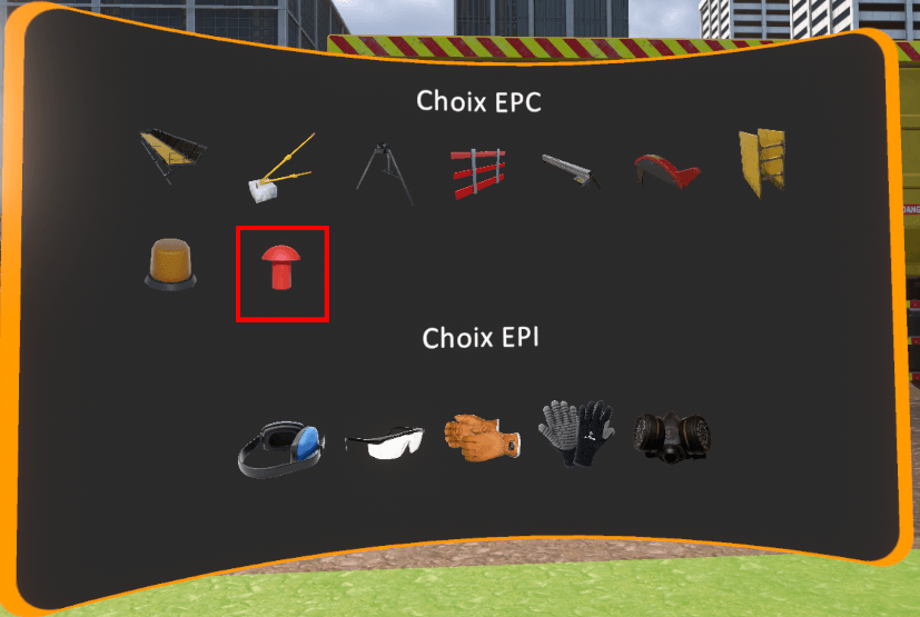
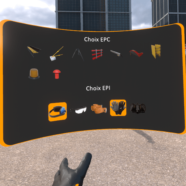
A screen appears in front of the user’s left hand with a list of risk pictograms. It is possible to select a pictogram using the right hand by pointing and clicking on the interaction key.
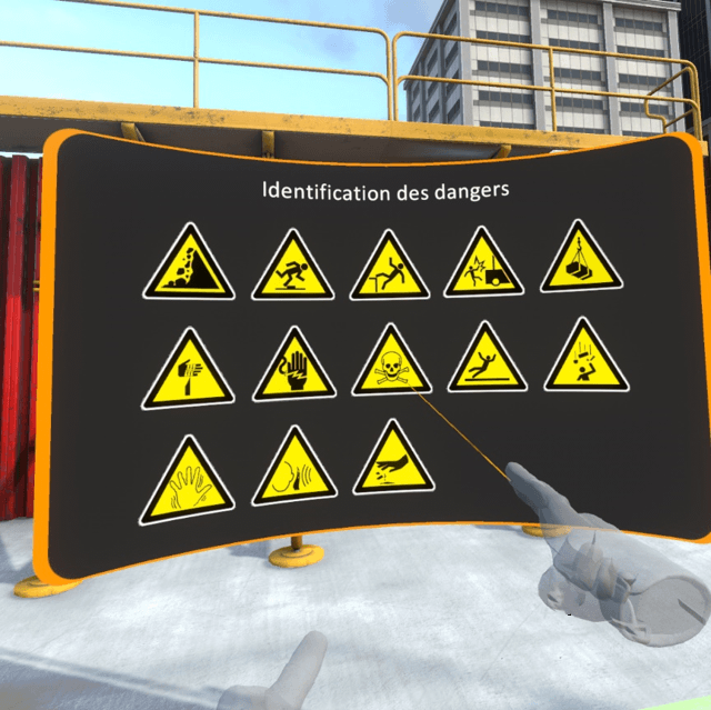
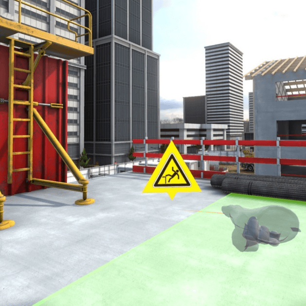
Once a pictogram is selected, the latter appears framed in orange. Now the user must point in the 3D scene at the exact location (or nearby) the risk that he wishes to identify and press again on the interaction key to place the pictogram on it.
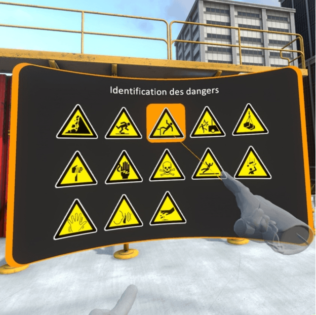
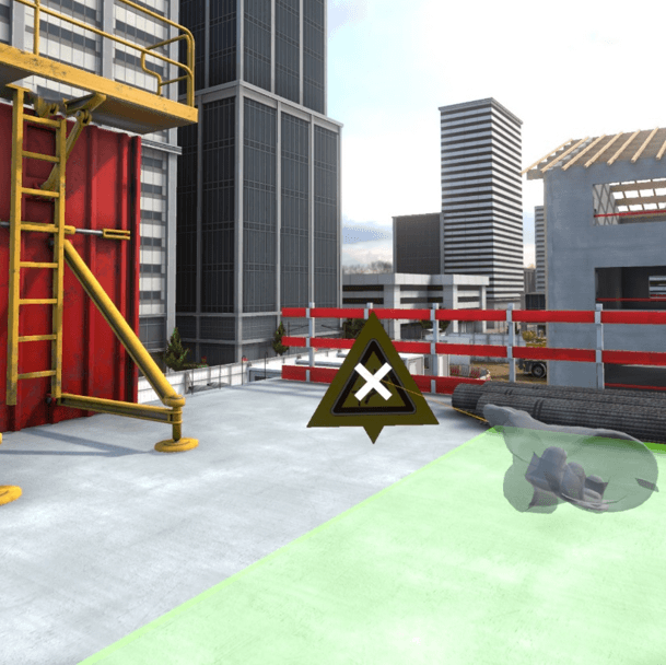
It is possible to delete a positioned pictogram by pointing at it and clicking on the cross.
Once all risks have been identified, the user must click on the buttom “Validate the identification” on the tablet at the level of the left wrist.
7.2.2. Securing procedure
Once dangers have been identified, the user is asked to secure the zone. The securing phases depend on the type of each risk, the security procedure for each workstation will be described later.
Once the workstation has been secured, clicking on the button « Validate securing » of the tablet enables the user to move on to the next step.
Once the identification of the security procedure has been completed on the first workstation, the user is asked to move on to the next workstation until he has completed all of the workstations in the zone.
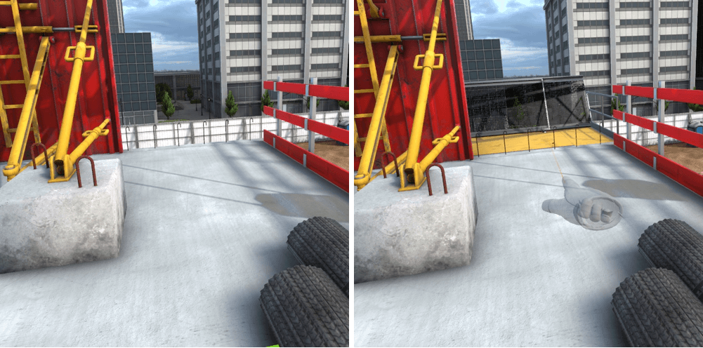
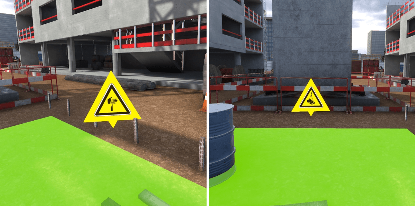
7.2.3. Zone assessment
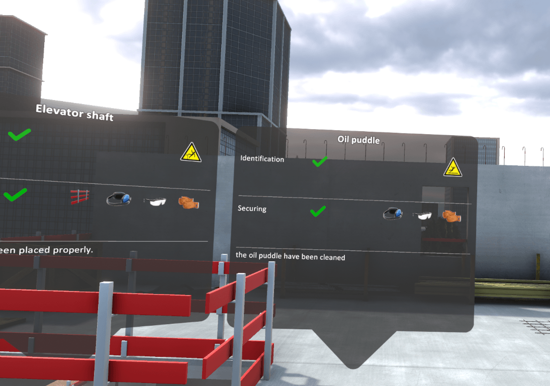
Once all the workstations have been completed, it is possible to move freely in the zone. Pop-ups on the different risks summarize if they have been correctly identified and secured.
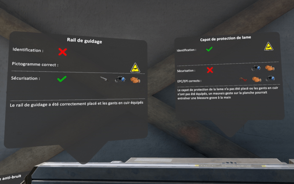
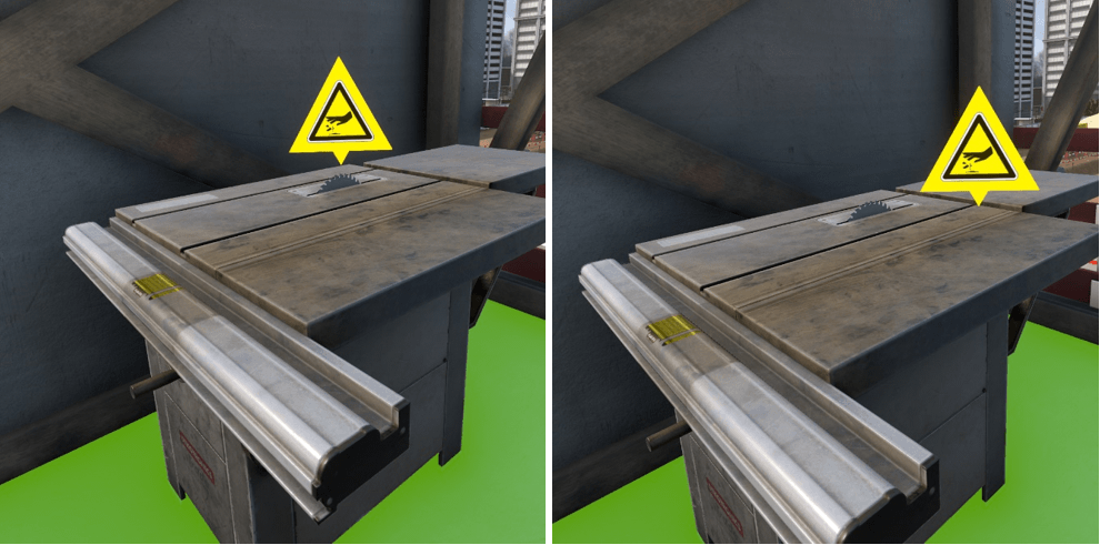
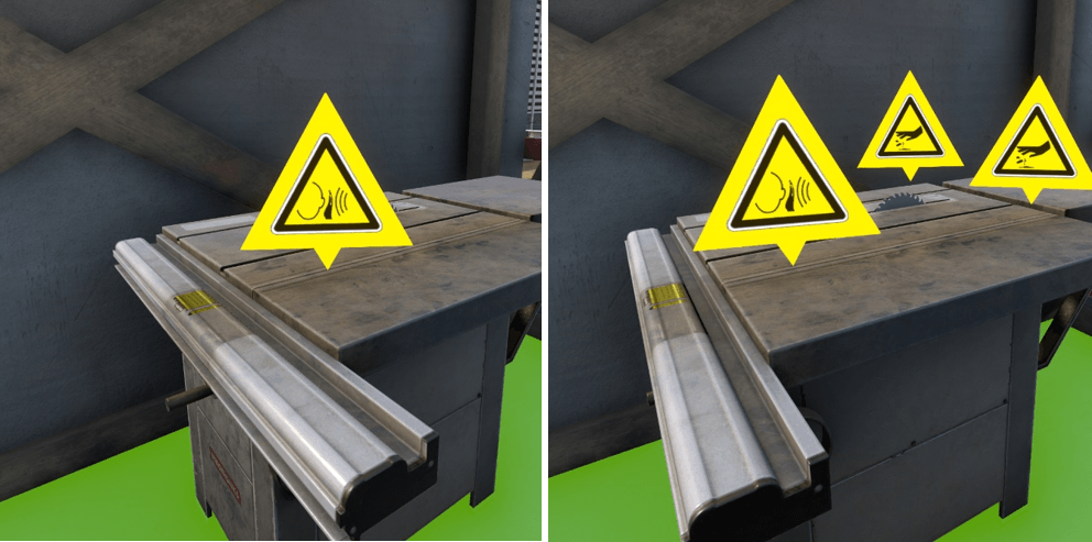
On the example above, the danger corresponding to the guide rail, has not been identified, no pictogram has been placed, so the correct pictogram is displayed. The security is correct, the blade guide has been placed, and the leather gloves and noise protection equipped.
For the danger of the blade protection cover, it was correctly identified by placing the pictogram but it has not been correctly secured. You can see that the gloves and noise protection gear have been equipped, but the cover has not been placed on the blade.
It is possible to terminate the exercise by clicking on the tablet cross, or by going on to the red marker on the ground.

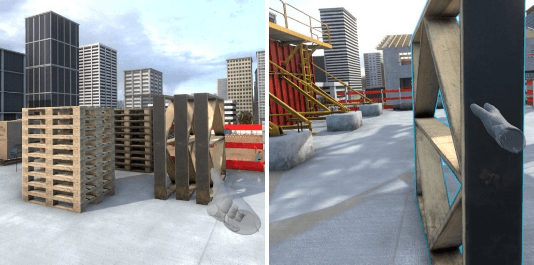
7.2.4. R+2 Structural work area
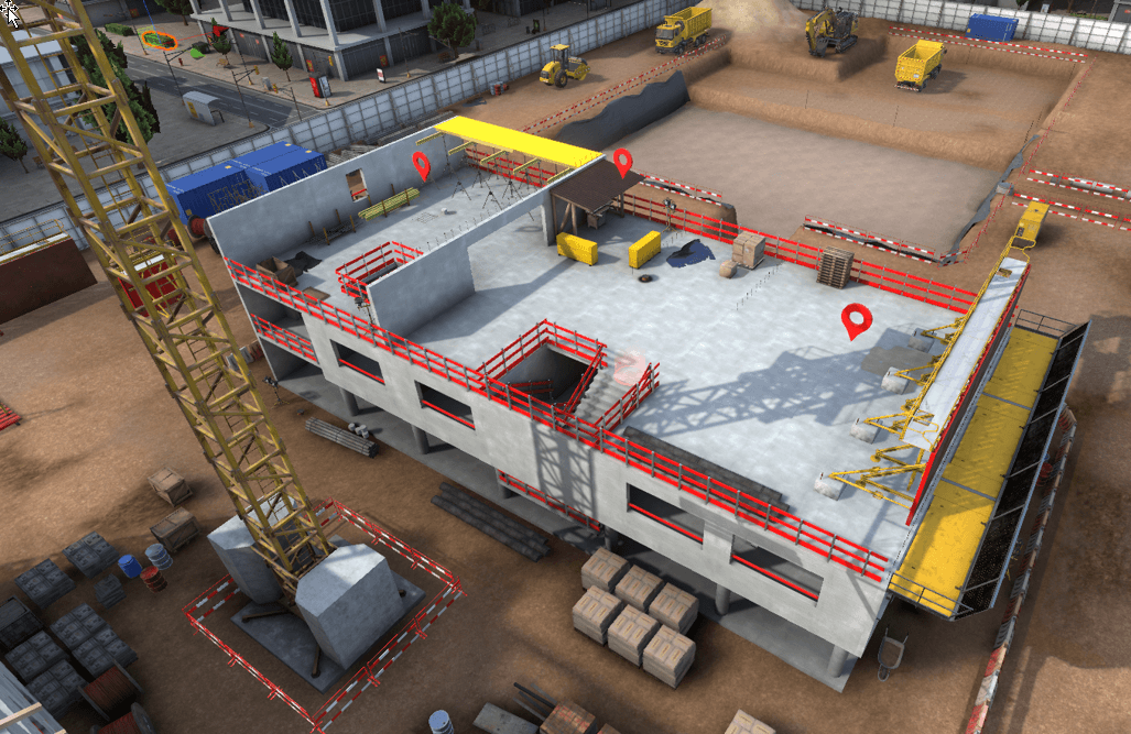
Upon arrival on the zone, three workstations are available, it is possible to move freely to one of the three workstations to begin the risk identification.
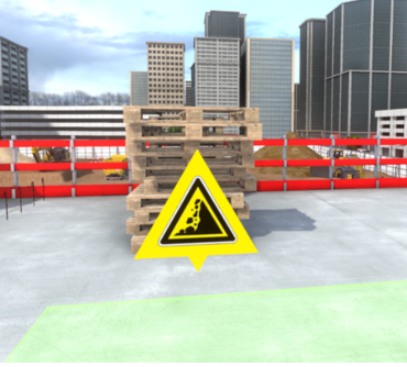
Workstation 1 – Coffrage de voile banché /Formwork for a
reinforced wall
There are three dangers on this workstation :
-
Unstable pile of pallets
-
Missing concrete ballast on the formwork
-
Missing platform
Identification
Ensuring security
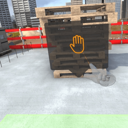
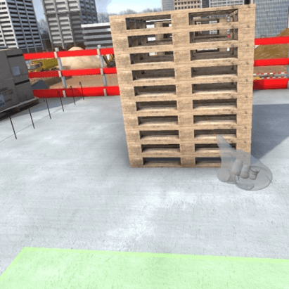
To secure the pile of unstable pallets, the user must get close enough to it for a pop-up to appear. A click on this pop-up will result in the pallets being positioned in a more stable position.
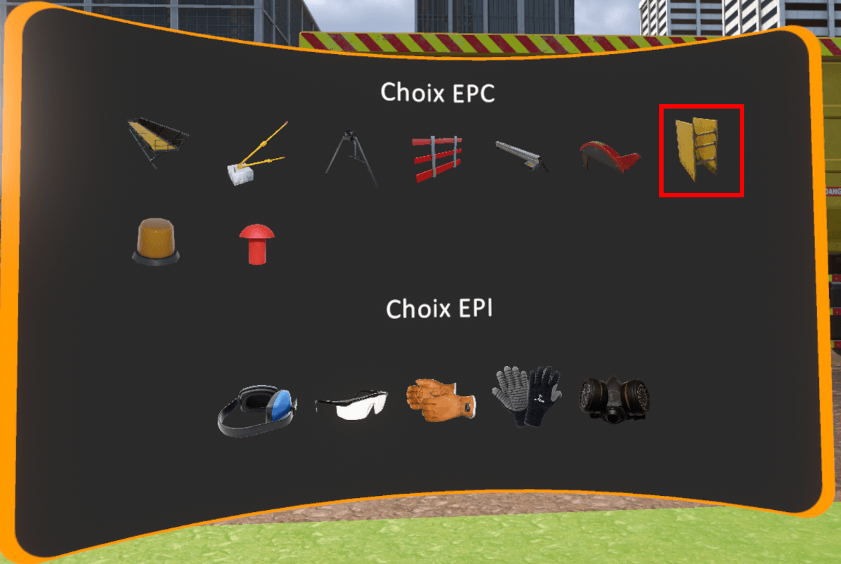
To secure the panels in danger of falling over, click on the « concrete ballast » PPE on the equipment selection window then point to the ground in front of the panels. Then click on the interaction key. This will result in placing the concrete weights against the panels to stabilize them.
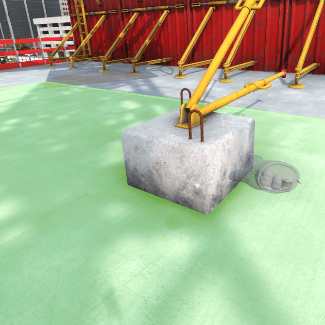
To secure the void near the panels, the user must select the platform in the list of PPE available and point the controller in the direction of the void. Clicking on the interaction key will position the platform in the right place.
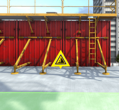
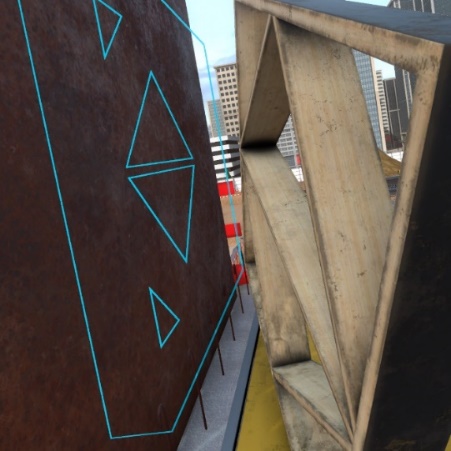
Workstation 2 – Cutting formwork panels
There are three dangers on this workstation :
-
Lack of blade guard
-
Missing guide
-
Saw noise
Identification
Securing procedure
To secure the blade, select the blade guard in the list of PPE available then point and click on the saw blade with the interaction key. This will position the blade guard on the blade. It will also be necessary to put on the leather gloves available in the list of PPE.
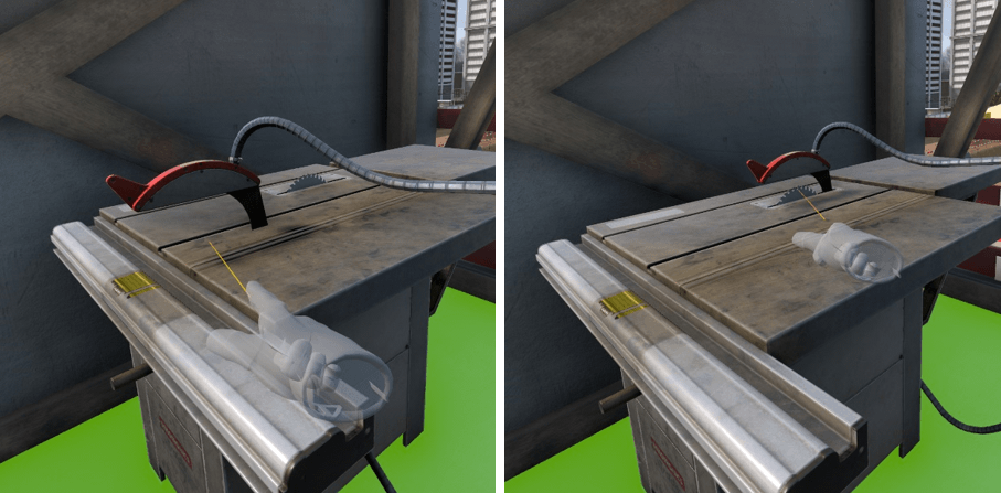
To secure the cutting, it is necessary to install the missing blade guard. It can be found in the list of PPE and positioned by clicking and pointing with the interaction key.
The third danger in the zone concerned is the noise of the saw.
To protect yourself from the noise, the noise protection gear must be equipped from the list of PPE in addition to the leather gloves.
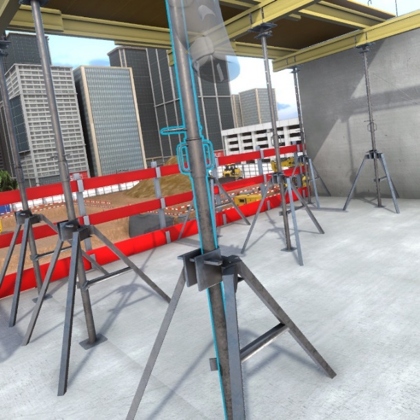
Workstation 3 – Formwork floor shoring
There are three dangers on this workstation :
-
Missing guardrail
-
Oil stain
-
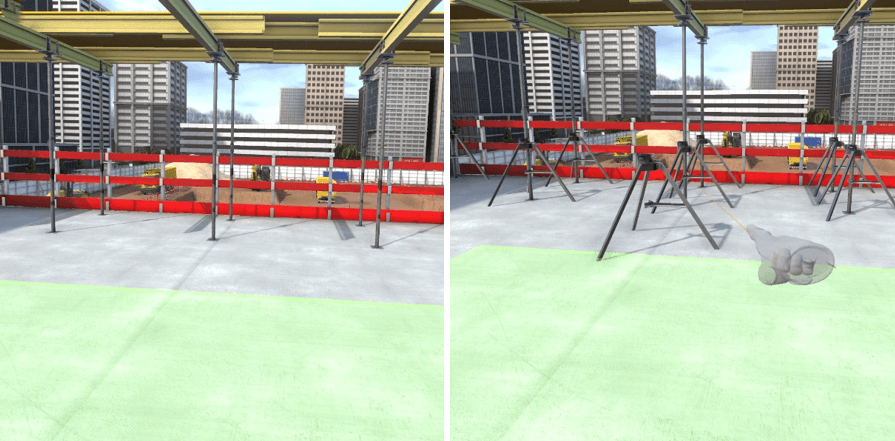
Lack of tripods on props.
Identification
Ensuring security
To secure the void at the elevator shaft, you must select the guard rail from the list of EPC, point at the void and click on the interaction key.
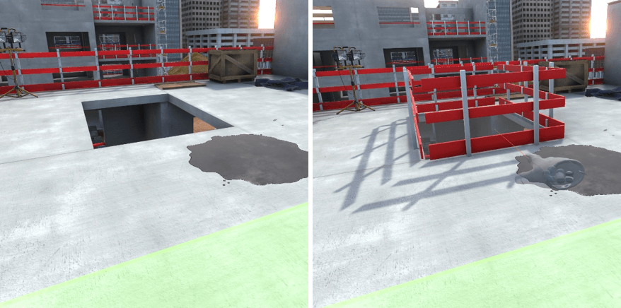
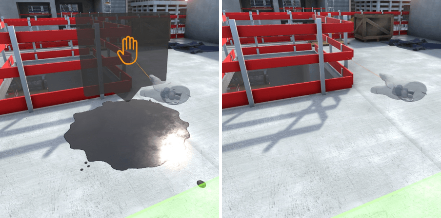
To eliminate the oil stain on the ground, you must get closer to it till a pop-up appears. Clicking on the pop-up will eliminate the oil stain.
To position the tripod on the props, they must be selected in the list of PPE then point in the direction of a prop and click on the interaction key. They will be positioned on the ground.
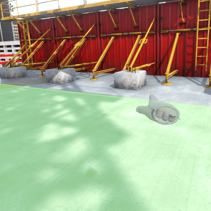
7.2.5. R0 Zone structural work preparation
Upon arrival at the zone, two work stations are available, it is possible to move around freely at one of the two work stations to begin the risk identification.
Workstation 1 – Lifting of scaffolding packages
There are two dangers on this workstation :
-
Unprotected holding steels
-
Crane.
Identification
Ensuring security
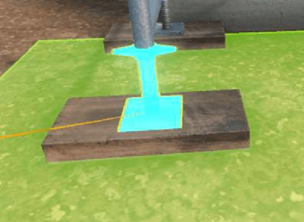
To secure the unprotected holding steels, you must select the steel protection end caps from the list of PPE and place them on the holding steels on the ground.
The danger due to the crane can’t be secured, it is necessary to make sure not to get close to the load carried by the crane when it manoeuvres.
Workstation 2 – Cleaning, preparation of the panels
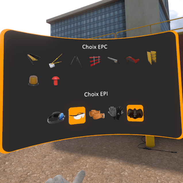
The dangers on this workstation are related to the toxicity of the form release agent.
Identification
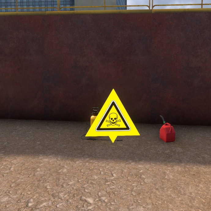
Ensuring security
To secure this workstation, it is necessary to equip two PPE available on the PPE selection screen. A gas mask to protect against toxic fumes from the form release agent as well as protective glasses to prevent any projections in the eyes.
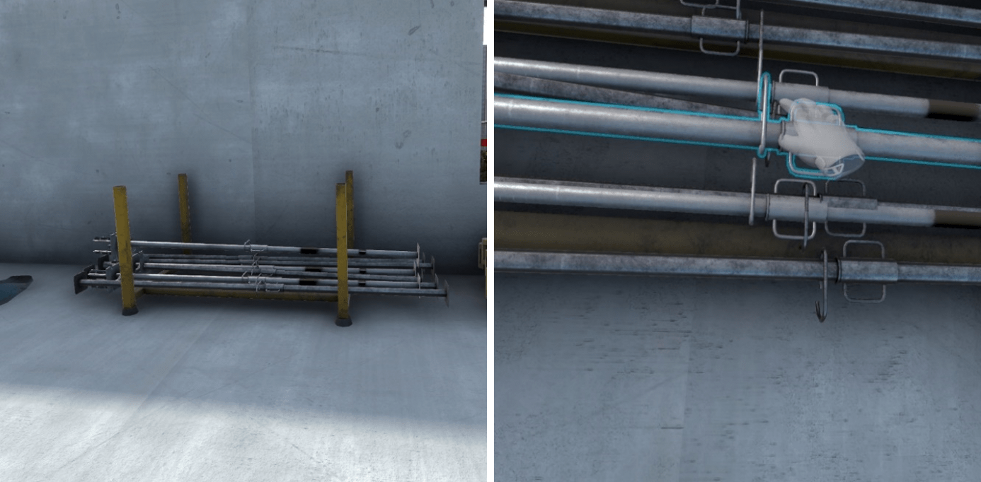
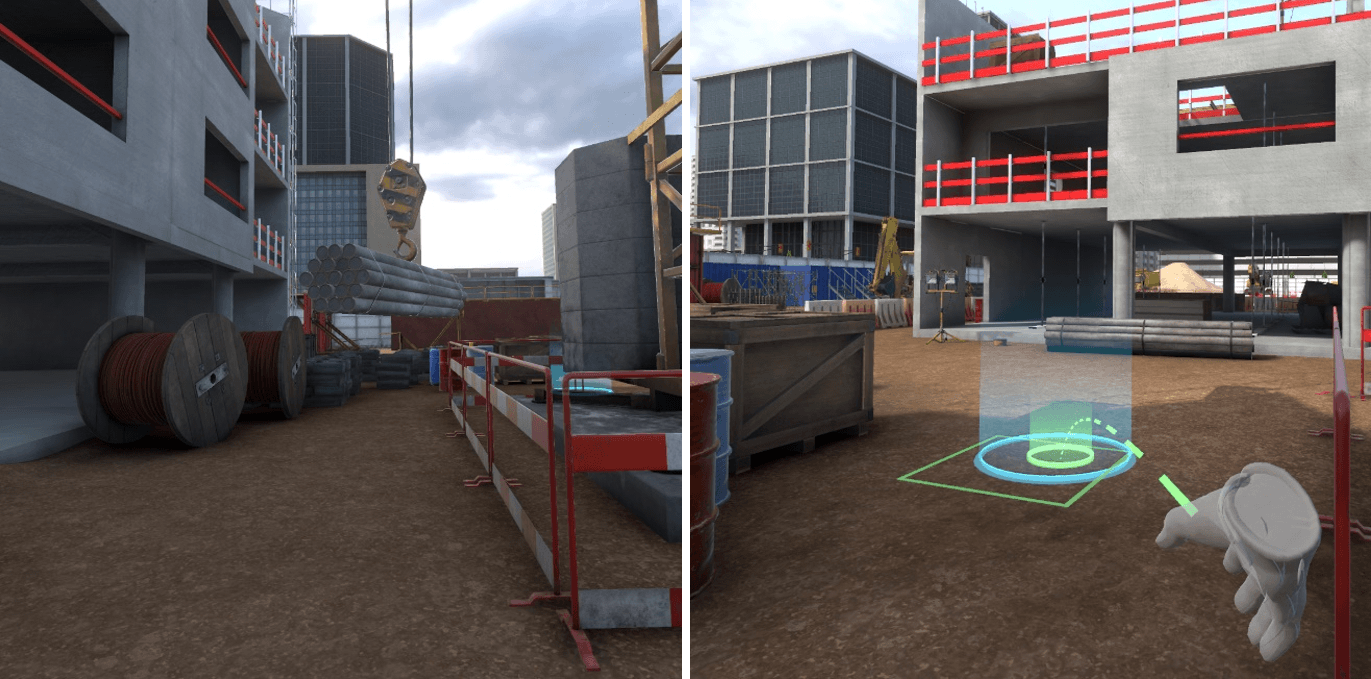
7.2.6. R-1 Earthwork area
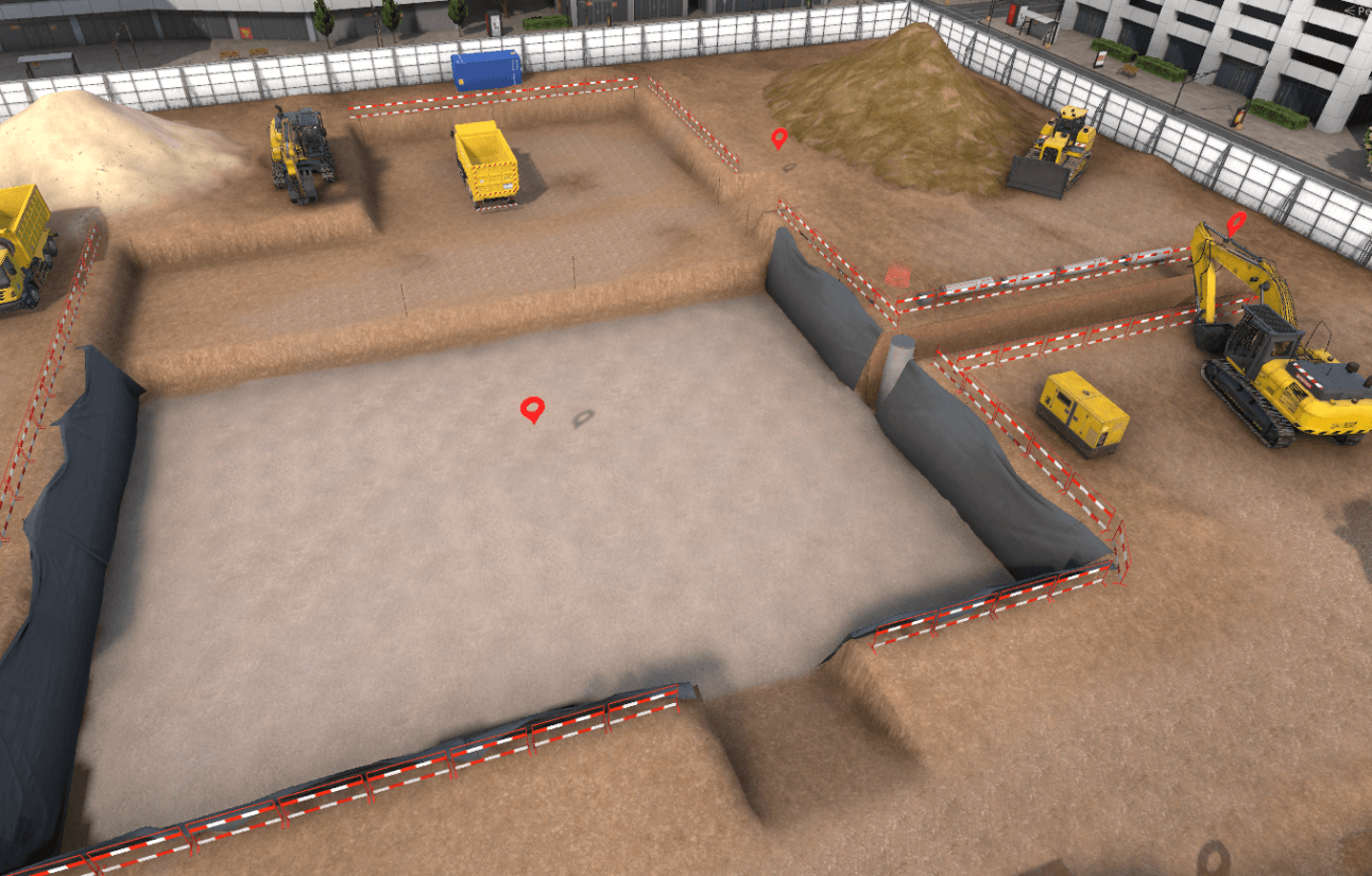
Upon arriving at the zone, three workstations are available. It is possible to move freely at one of the three workstations to begin the danger identification.
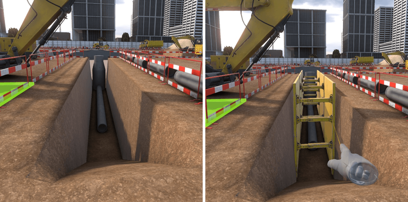
Workstation 1 – Laying a pipe at the bottom of the trench
There are two dangers at this workstation:
-
A pipe is at the edge of the trench and could fall into the trench. et pourrait basculer dans la tranchée.
-
The walls of the trench are not supported by shoring and could collapse.
Identification
Ensuring security
To secure the pipe, you need to get close enough for a pop-up to appear. Clicking on this pop-up will position the pipe in a less dangerous position.
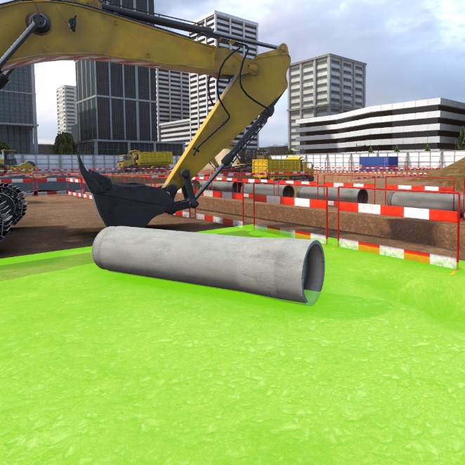
To secure the trench, first select shoring in the list of PPE available, then place them by pointing and clicking on the trench walls.
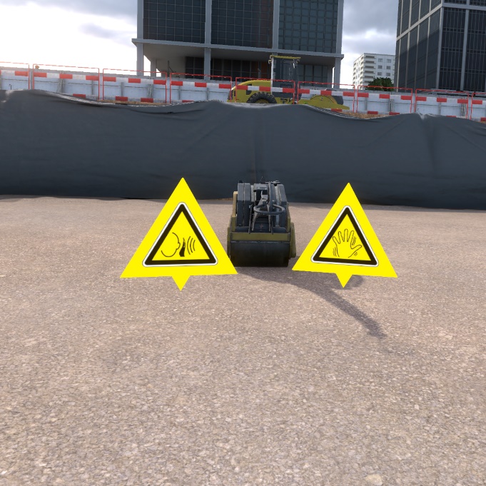
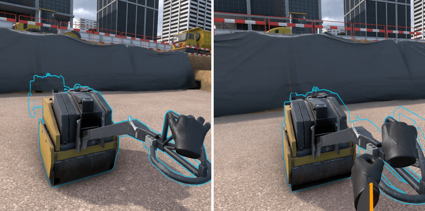
Workstation 2 – Soil compacting
The dangers on this workstation are the intense noise of the compactor, and the strong vibrations under usage.
Identification
Ensuring security
To secure this workstation, it is necessary to equip the anti-vibration gloves as well as hearing protection muffs, which are both available in the PPE list.
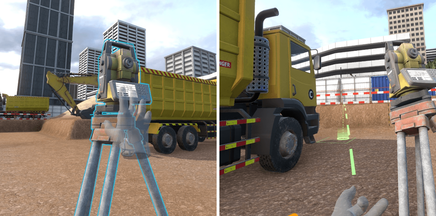
Workstation 3 – Topographic control of the platform
The danger on this workstation is the truck getting ready to back up.
Identification
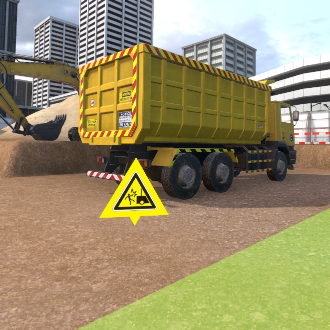
Ensuring security
For the security phase, select the flashing light from the list of PPE and place it on the truck by pointing at it and clicking on the interaction key.

7.3. Evaluation
In evaluation mode, the user is asked to perform an action on the construction site. He or she has the possibility of securing the dangers that he encounters. If he does not do it, and he puts himself in danger, a fatal error takes place which puts an end to the exercise. There is an evaluation exercise per workstation available on the construction site.
Exercise evaluation criteria
![]() Ensuring security : capacity to see and correct the dangers before
arriving at the workstation.
Ensuring security : capacity to see and correct the dangers before
arriving at the workstation.
![]() Execution time : capacity to finish the scenario in a defined time
Execution time : capacity to finish the scenario in a defined time
7.3.1. R+2 - Workstation 1 – Wall formwork
IInstruction :
Place a formwork dummy at the highlighted location behind the formwork panels.
To complete this objective, grasp one of the formwork dummies placed near the palettes and place it on the blue highlighted zone behind the formwork panels. To do this safely, it will be necessary to secure the different zone dangers including:
-
Stabilizing the pile of pallets by getting close to them and clicking on the popup
-
Placing the concrete weights against the formwork panels
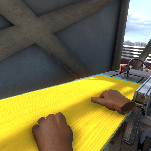
7.3.2. R+2 - Workstation 2 – Formwork panel cutting
Instruction : Cut the formwork panel present on the cutting station.
To complete this objective, simply grasp the formwork panel placed on the saw and move it to perform the cut.
To do this safely, first you must :
-
Place the blade guard on the saw
-
Place the blade guide on the platform
-
Put on the leather gloves
-
Put on the noise protection gear.
7.3.3. R+2 - Workstation 3 – Floor shoring formwork
Instruction : take a prop from the basket and place it in the highlighted location.
To complete this objective, grasp a prop in the basket and place it at the location highlighted in blue being careful to first secure the zone so as not to set off a fatal error:
-
Clean up the oil spot by carefully getting close to it and clicking on the pop-up that appears over it.
-
Position guard rails around the elevator shaft vide
-
Place tripods around props.
7.3.4. R0 - Workstation 1 – Lifting scaffolding packages
Instruction : Go to the highlighted spot safely.
To complete this objective, go to the blue marker located around the crane, being careful to place the protective end caps on the steel holders on the ground. You must also wait for the passage of the crane carrying the load before passing to avoid being hit.
7.3.5. R0 - Workstation 2 – Cleaning, preparation of the panels
Instruction : Spray the form release agent on the formwork panels
To complete this objective, grasp the spray with the objective grasp button then press on the interaction key to spray the product. Before doing this, to be safe, you must :
-
Put on the gas mask
-
Put on the protective glasses.

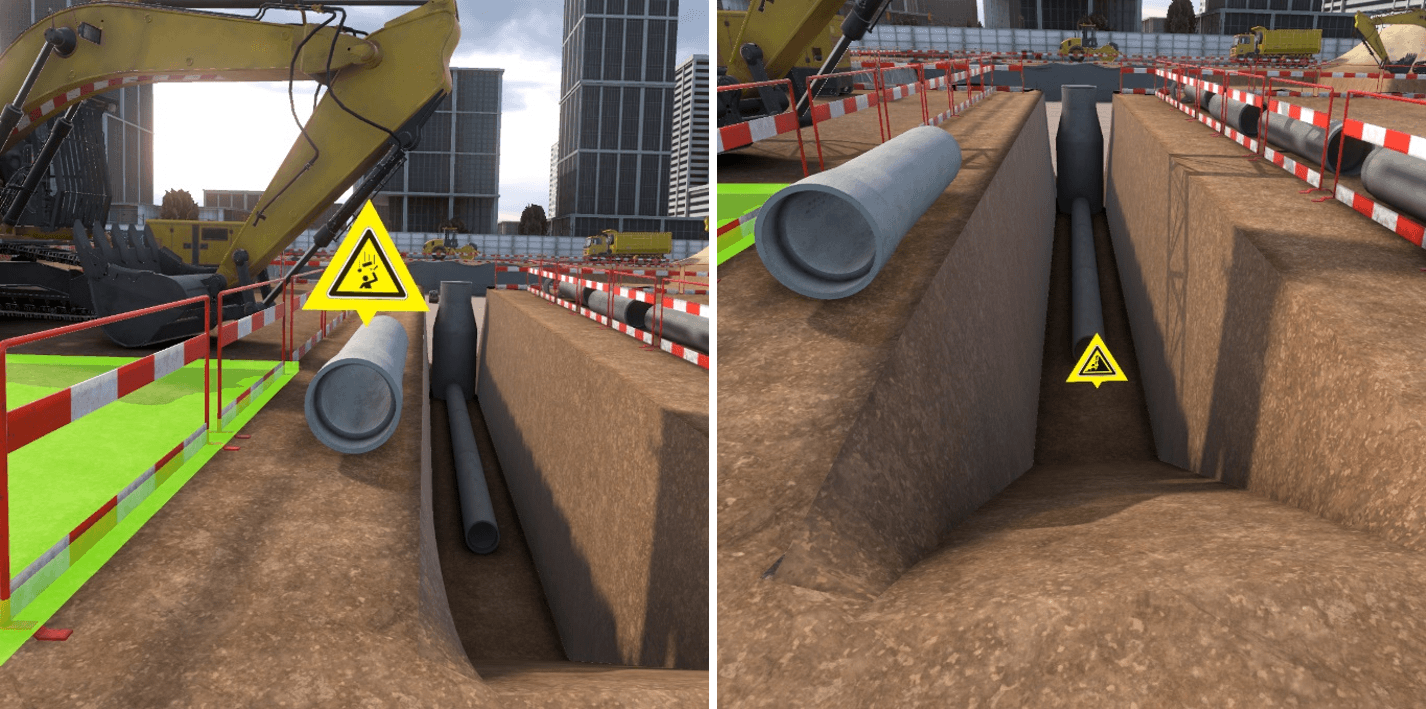
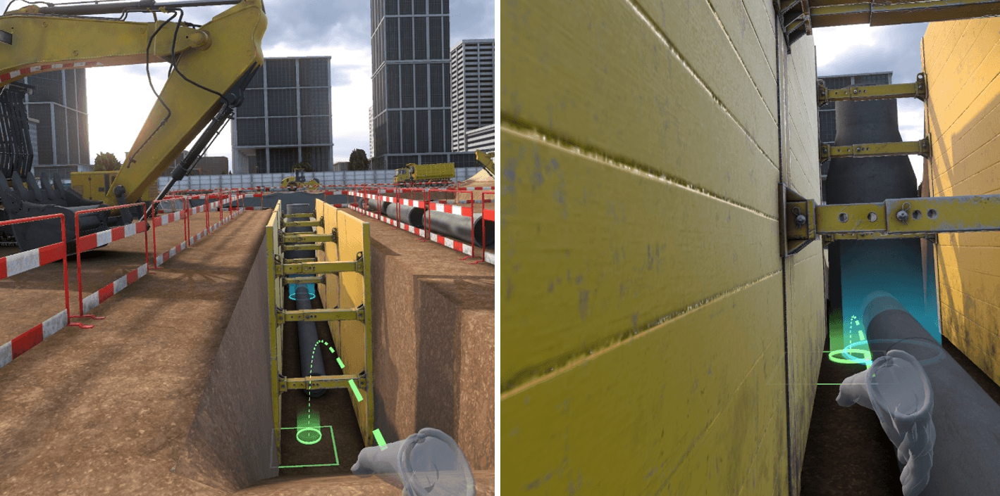
7.3.6. R-1 - Workstation 1 – Laying pipe in the bottom of the trench
Instruction : go down into the trench at the highlighted location to control the slope of the waste water pipes.
To complete this objective, you must enter the trench at one end on the blue marker and stay there a few instants:
First you must :
-
Move the pipe that risks falling into the trench by getting closer and clicking on the pop-up that appears over it.
-
Place shoring on the trench walls to prevent collapse.
7.3.7. R-1 - Workstation 2 – Soil compacting
To complete this objective, grasp the compactor with the object grasp key and keep pressing the key till the compactor reaches the highlighted zone. First you must secure the situation:
-
Put on anti-vibration gloves available in the PPE list.
-
Put on the noise protection gear available in the PPE list.
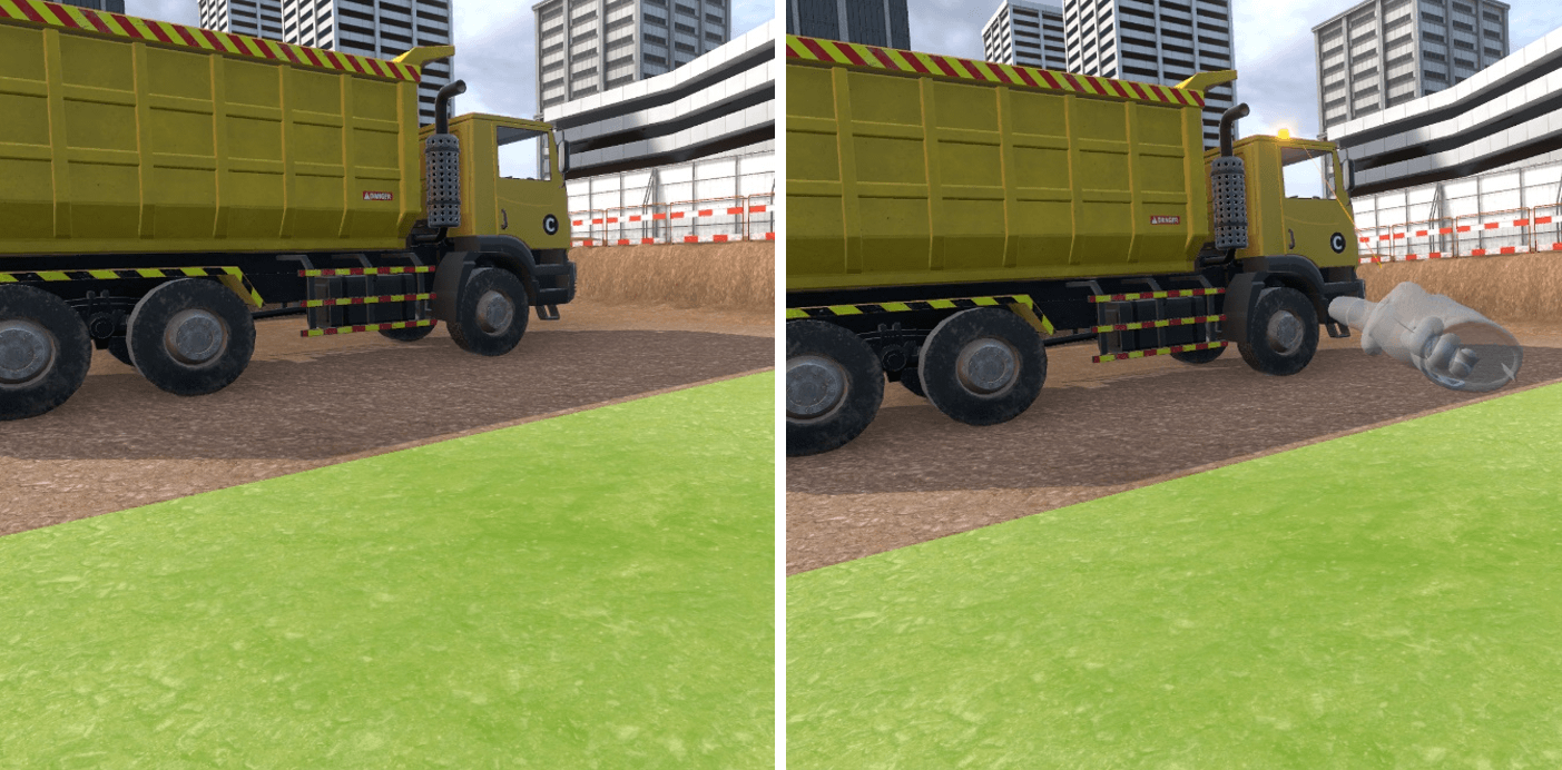
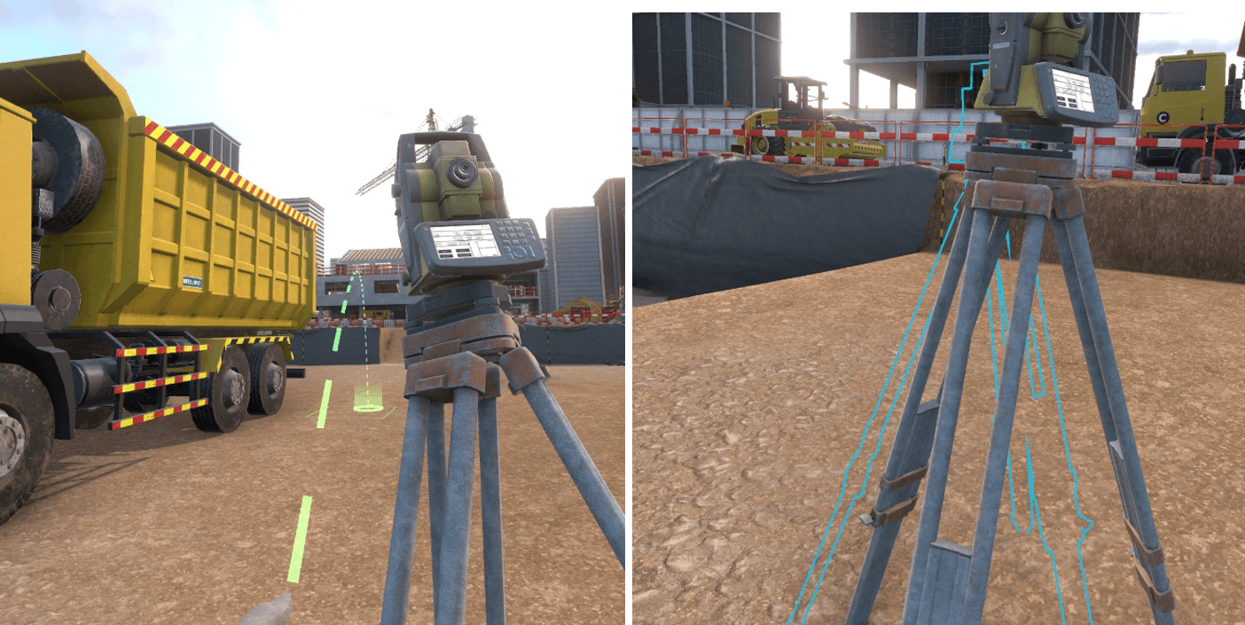
7.3.8. R-1 - Workstation 3 – Topographical control of the platform
Instruction : Move the tacheometer to the highlighted location to make a measurement
To complete this objective, take the tacheometer by pressing on the object grasp button and holding it down. Then walk around the front of the truck and place the tacheometer on the blue highlighted zone. First place the missing flashing light on the truck by selecting it in the PPE list and clicking on the truck with the interaction key.
7.4. Setting up the exercises
The default exercise settings can’t be changed but it is possible to create editable copies whose settings can be changed by the trainer to vary the grading according to several criteria.
7.4.1. Parameters
Name of the exercise : enables to change the name of the exercise as it is displayed in the simulator
Level : corresponds to the level of the exercise, when copying an exercise by default it is important to not modify this parameter (beginner = free mode, advanced = guided mode, expert=evaluation mode)
Validation threshold : corresponds to the value of the final score (percentage) below which the exercise is considered a fail.
Consideration threshold : score below which the result of the exercise will not be taken into account.
7.4.2. Sensors
| Min | Target | Max | |
|---|---|---|---|
FREE MODE |
|||
Distance travelled |
Distance in meters to travel below which the score will be 0 % |
Distance in meters to travel starting at which the score will be 100 % |
|
Time before an accident |
Duration in seconds spent on the exercise below which the score will be 0 % |
Duration in seconds spent on the exercise starting from which the score will be 100 % |
|
ACCEPTANCE and USE |
|||
Identification |
Number of dangers identified to obtain a score of 100 % |
Indicative value of the number of dangers present on the zone for this exercise (should not be modified) |
|
Securing |
Number of dangers secured to obtain a score of 100 % |
Indicative value of the number of dangers present on the zone for this exercise (should not be modified) |
|
Duration of execution |
Duration in seconds spent on the exercise below which the score will be 100 % |
Duration in seconds spent on the exercice above which the score will be 0 % |
7.4.3. Simulation variable
Percentage of malus per identification error: percentage of malus applied to the identification score for a danger in this exercise, for each incorrect picture placed in addition to a correct picture (for example, for a value of 10 at this variable, if a correct picture is placed as well as an incorrect picture near the same risk, a malus of 10% will be applied to the identification score for this risk).
Percentage of malus per securing error : percentage of malus applied to the securing score for a risk of this exercise, for each attempt to place an incorrect PPE at the expected securing location.
Percentage of malus per extra PPE equipment : percentage of malus applied to the securing score for a danger of this exercise, for each additional un-necessary PPE equipped. (example: the value of the variable is 10, a risk requires wearing noise protection muffs but protective glasses are also equipped, so the malus would be 10% on the securing score for this risk).
8. Scaffolding Safety Module
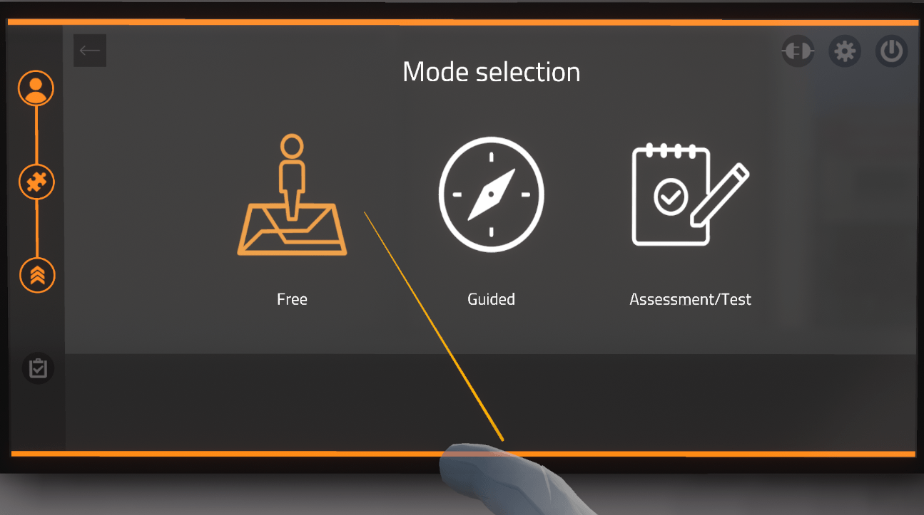
8.1. Modes
This section the different modes that are available in Virtual Construct Scaffolding Safety
The available modes are :
-
Free mode
-
Guided mode
-
Assessment / Test mode
8.1.1. Free Mode
In free mode, the user moves about freely on the construction site. All the possible dangers on the construction site are present and fatal errors may occur if the user gets too close to one of the dangers. If the user becomes a fatality, he then respawns in the locker room and has to start over.

The user passes the exercise if they are able to cover a required distance in a specified time period. Both the distance and time parameters are set by the instructor in Vulcan (more detail on Vulcan at the end of the document).
In this mode, the user does not have the possibility of securing any dangers that he encounters and can leave the exercise at any time by clicking on the cross on the top right corner of the tablet on his left wrist.
When the user is finished, the time and distance statistics are displayed on the menu screen.
The evaluation criteria are:
-
Reaching the floor objective
-
Exceeding the target time "Time to accident"
8.1.2. Guided Mode
The user can select from two different scaffolding sites to use, facade and multidirectional scaffolding. They can be completed in any order.
After selecting an exercise, the user moves to a station which is identified by a red pin floating above it.
Once under a marker, the user is given instructions on the tablet and through the headset.
After one exercise is completed then the user is transported to the locker room and needs to complete the other exercise.
The exercises are described in greater detail later in this document.
8.1.3. Assessment / Test Mode
This mode tests the user on the knowledge they have acquired as they have completed the various exercises.
The user selects Assessment/Test Mode from the three choices on the main menu and then selects which exercise they are to be tested in.

During the Assessment/Test Mode, the user gets instructions on their tablet as well as through the headset.
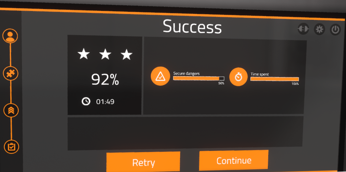
When the user is finished each section of the evaluation, the results are displayed floating beside each station.
When the user is completely finished the evaluation, the final results will be displayed on the main menu. The user will then have the choice to retry that specific evaluation or continue on to the next evaluation.
8.2. Guided Mode Exercises (Reception Exercises)
In guided mode, the user will be helped at each phase of the exercise with screen tips and audible tips. The user is invited to correct any mistakes as he or she goes along to assimilate best practices.
The evaluation criteria are:
-
Analysis: relevance of the user’s answers during the preparation phase
-
Scenario: validation of all of the steps of which the scenario is comprised
-
Identification: capacity to recognize assembly flaws
-
Execution time: capacity to finish the scenario in a defined time
Both Guided Mode exercises start the same way so the procedure will be explained here and then any differences will be explained in the appropriate subsection below.
The following steps must be completed:
8.2.1. Select exercise
User selects an exercise to complete
8.2.2. Receive instructions
The screen changes to an instruction screen. Click on the Interactive Button to hear a voice read it to you.
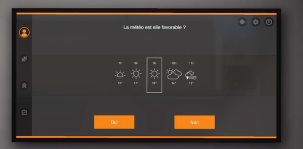
8.2.3. Select weather
After validation, a weather forecast appears. The user must determine if the weather conditions are favourable scaffolding work on the construction site.
8.2.4. Get PPE
Turn to the left and an open locker is visible with an interface enabling the user to choose the equipment to wear. If the user makes a poor choice, this is highlighted, and the user has to correct the error before moving on to the next phase. Once the user has selected the equipment, click on the checkmark on the right hand side of the screen
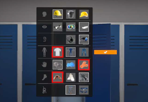
The correct PPE to select is:
|
Hardhat with strap |
|
Protective glasses |
|
Ear protectors |
|
Coveralls |
|
Work gloves |
|
Saftey boots |
|
Harness |


8.2.5. Select location
The user is automatically brought to the work site and has to choose the location that corresponds to the exercise. Teleport to the desired location.

The next steps are specific to their own type of scaffolding and will continue in their appropriate sub-section.
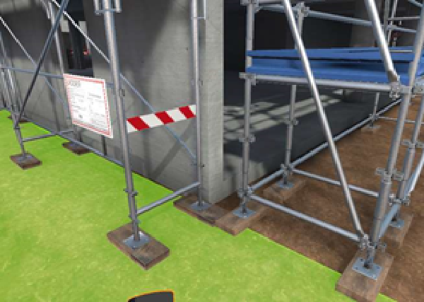
8.3. Facade Scaffolding
In this exercise, the user must evaluate the quality of the mounting of the scaffolding and identify any flaws. All the faults must be found with the scaffolding before the exercise can be completed. The user has to identify all the faults on a level before using the ladder to climb up to the next level.
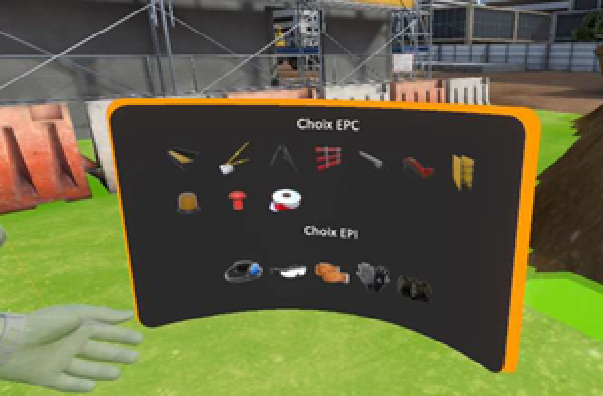
8.3.1. Mark work area
The user is required to select the appropriate PPE and cution tape to mark the scaffolding as off-limits.
8.3.2. Check anchors
The user then has to look at the scaffolding construction plans and ensure they have been followed. On the top right hand corner of the Tablet, click on the "Highlight Anchors" button. This will highlight in green all the anchors on the scaffolding.
8.3.3. Identify dangers
The aim here is to methodologically identify all the scaffolding assembly flaws, floor by floor. As mentioned earlier, all the faults must be identified before the user is allowed to go up to the next floor. The faults are generated randomly as a function of the instructions given by the trainer on the Vulcan platform, so that each session is different for each user.
With the help of a laser, the user will highlight the parts that he considers to be defective or incorrectly assembled. The parts selected by the user appear highlighted in Cyan.
It is during this phase that the correction intervenes in Guided mode: if some flaws have not been identified by the user, the trap door will not open and the forgotten flaws will be highlighted in red, with a message indicating the mistake. The student must correct all mistakes before being able to reach the following level.
Once the user has identified all the flaws on a floor, he moves on to the next floor by using the ladder and oging through the trap door.
The possible faults are shown in the table below:
| Part | Flaw | Photo |
|---|---|---|
Anchors |
Incorrect anchors |
|
Base jack |
Missing nibs |
|
Plateau or tray |
Deformed retaining hook |
|
Metal planking |
Deformed |
|
Metal planking |
Oxidized |
|
Metal planking |
Retaining hook deformed |
|
Walk through frame |
Deformed |
|
Walk through frame |
Oxidized |
|
Guard rail |
Deformed |
|
Guard rail |
Oxidized |
|
Toe board |
Incorrectly installed |
|
Toe board |
Wrongly posioned |
|
Ladder |
Broken rung |
|
Ladder |
Broken hook |
|
Top rail |
Hook not secured |
|
Planking |
broken cable |
|


8.3.4. Multidirectional scaffolding
The guided mode for multidirectional scaffolding is identical to the guided mode for facade scaffolding. The difference is the type of scaffolding the user is required to assess.
8.4. Usage Exercises
This exercise gives the user practice with the use of scaffolding by different trades. The scaffolding is considered to have already been approved and controlled; so the aim of the exercise is to acquire good daily practices.
Such as:
-
IPE management
-
Sign verification
-
Movement between the floors
-
Obstacle management
There are four different modes corresponding to four different trades:
-
Finishing
-
Study of constructions
-
Structural work
-
Wood framing
Each trade will starting in a different zone, depending on the trade.
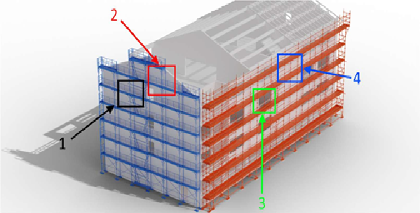
The evaluation criteria, for this exercise is as follows:
-
Analysis : relevance of the learner’s answers during the preparation phase
-
Scenario : validation of all the phases that make up the scenario
-
Identification : capacity to see and rectify obstacles on the user’s path
-
Execution time : Capacity to finish the scenario in a defined time
8.4.1. Starting the exercise
The following steps must be completed:
Select exercise
User selects an exercise to complete.
Receive instructions
The screen changes to an instruction screen. Click on the Interactive Button to hear a voice read it to you.
Select scaffolding
The user must select the type of scaffolding to be used.
Select weather
After validation, a weather forecast appears. The user must determine if the weather conditions are favourable scaffolding work on the construction site.
Get PPE
Turn to the left and an open locker is visible with an interface enabling the user to choose the equipment to wear. If the user makes a poor choice, this is highlighted, and the user has to correct the error before moving on to the next phase. Once the user has selected the equipment, click on the checkmark on the right hand side of the screen.
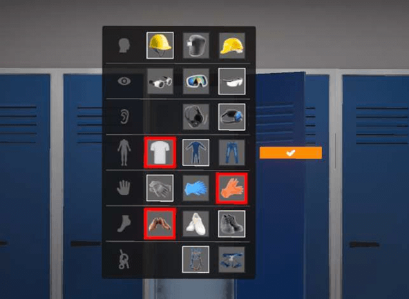
Arriving at site
Once the preparation phase is finished, the user is teleported to the construction site and must choose what scaffolding corresponds to the mission. The choice is validated by moving on to the appropriate area indicated in purple.
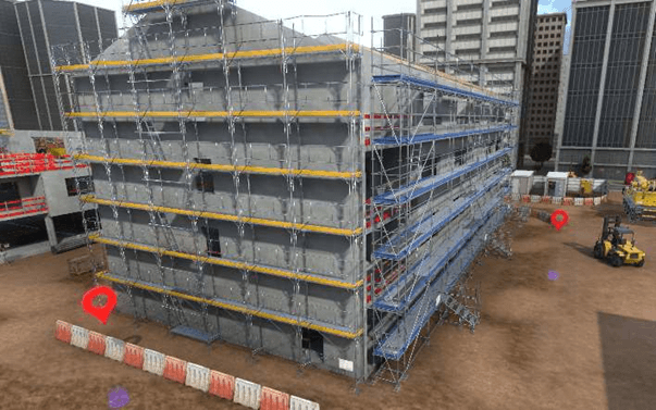
Ensure scaffolding specifcations
Before going on the scaffolding, the user must ensure that it’s specifications comply with the needs related to the trade selected iat the beginning of the exercise.
The user must read the sign to verify the maximum load is allowed:
-
Finishing : scaffolding bearing 200kg/m² or more
-
Construction studies : scaffolding bearing 150kg/m² or more
-
Structural work : scaffolding bearing 600kg/m² or more
-
Wood framing : scaffolding bearing 450kg/m² or more
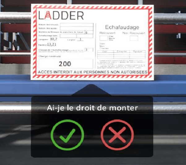
If the weight limit presented on the sign is not correct, and the user has answered the question, the value is automatically corrected to be able to continue the exercise.
Climb the scaffolding
The user can now mount the scaffolding. The simulator will evaluate his capacity to move around safely, in particular his capacity to close each trap door after himself. The user must move to the work area indicated by a red icon.
Clear obstacles
On the way to the objectives, the user may encounter obstacles: heavy loads or materials which block the passage. In this case, he will have to point at the object and click on the Interact Button to put them in their correct place.
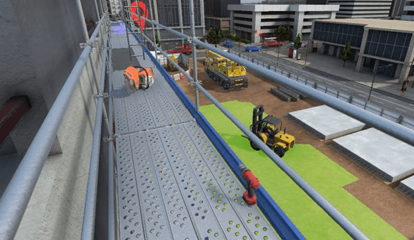
Move to purple circle
Once he has reached the intervention site, the user must walk to the purple circle. A sound confirms that the work went well.
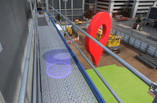
Climb down
The user then must climb down the scaffolding, always maintaining all the saftey rules. It is impossible to teleport off the top of the scaffolding. Move to the purple circle where the exercise started and the user will then be teleported to the locker room where the results will be shown.
The exercise is now complete.
8.5. Assessment / Evaluation Mode Exercises
In evaluation mode, the user doesn’t receive any hints and mistakes will be controlled at the end of the exercise.
The criteria for evaluating are:
-
Analysis: relevance of the user’s answers during the preparation phase
-
Scenario: validation of all of the steps of which the scenario is comprised
-
Identification: capacity to recognize assembly flaws
-
Execution time: capacity to finish the scenario in a defined time
For both the facade and multidirectional scaffolding assessment, the user is required to find all the faults but no hints are given. If the user misses a fault, it is considered to be a fatal error and the assessment is immediately stopped and the student fails. Once, the user has completed all seven floors, he moves to the purple circle at the end of the scaffolding to be teleported to the locker room where the results are shown.
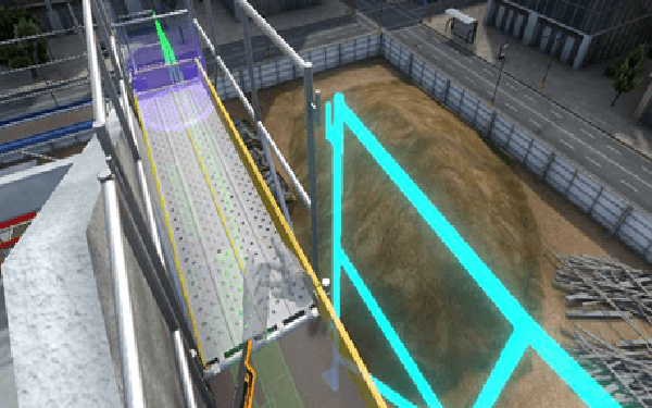
8.6. Score sceen
At the end of each exercise, a score screen will be displayed with the user’s results for that particular exercise.
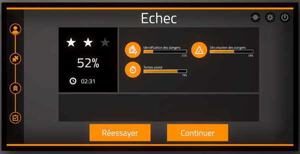
If a fatal error occurs, the exercise will immediately stop and the score screen will display the reason for the error and prompt the user to Retry or Continue.
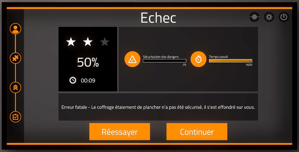
8.7. Vulcan Exercise Settings
The default exercise settings may not be modified, but it is possible to create editable copies of the exercises and then modify the parameters. This will allow the trainer to change the weight of the marking of each parameter (coefficient) based on different criteria.
The parameters that can be modified are:
Exercise Name |
makes it possible to modify the name of the exercise as it will be displayed in the simulator |
Level |
corresponds to the level of the exercise, it is important to not modify this parameter during the copy of an exercise by default (beginner=free mode, advanced=guided mode, expert=evaluation mode) |
Validation threshold |
minimum score required to pass the exercise |
Inclusion threshold |
score below which the result of the exercise will not be taken into account |
Percentage penalty per identification |
how much of a penalty for not identifying a fault |
Percentage penalty per securing error |
how much penalty for not securing a fault |
Percentage penalty per incorrect PPE |
how much penalty for choosing the wrong PPE |
8.7.1. Scaffolding safety sensors
This table shows what the saftey sensors can be set for and their minimum and maximum allowable values.
Min |
Target |
Max |
|
Floor objective |
0 |
Number of floors that the user must reach to pass the exercise |
7 (there are 7 floors) |
Time before an accident (seconds) |
Minimum amount of time user must spend in the exercise, anything less will result in 0 |
Duration spent on the exercise starting from which the score will be 100% |
Unlimited, but must be set to a number |
Execution time (seconds) (applies only ot Reception and Usage) |
0 |
anything below this will result in a score of 100% |
any time spent on the exercise above which will result in 0% |
The non-adjustable sensors in scaffolding are as follows:
-
Analysis
-
Securing
-
Identification
8.7.2. Scaffolding safety variables in Vulcan
It is possible to change some of the variables in the editable copy of the exercise in order to adjust for the difficuty and complexity of the exercise.
They are as follows:
-
Number of defects on individual floors: number of errors generated randomly on the floor concerned
-
Activate fatal errors: when the function is activated, a fatal error results if the user has forgotten to identify a fatal error on the current scaffolding floor
-
Number of obstacles on individual floors: when the function is activated, a fatal error results if the user has forgotten to identify a fatal error on the current scaffolding floor