1. Construction site safety (urban construction site)
1.1. Free Mode
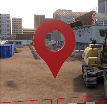
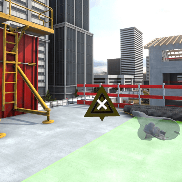
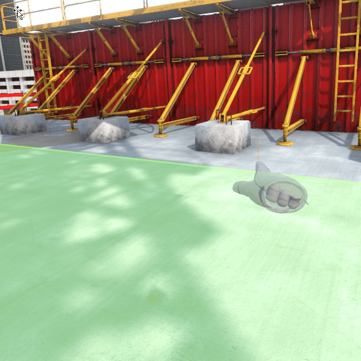
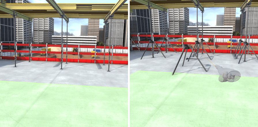
In free mode, the user can move freely on the construction site. All the possible risks on the construction site are present and fatal errors occur if the user gets too close to one of the risks. The exercise will be validated if the user is able to cover a distance indicated by the trainer in VULCAN in a defined time.
In this mode, the user does not have the possibility of securing the dangers that he encounters, and can leave the exercise at any time by clicking on the cross present on the tablet at his left wrist.
Exercise evaluation criteria
![]() Distance covered by the user
Distance covered by the user
![]() Time before accident
Time before accident
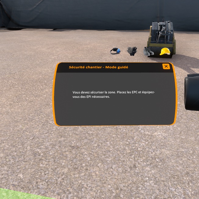
1.2. Guided mode
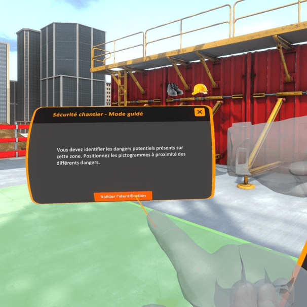
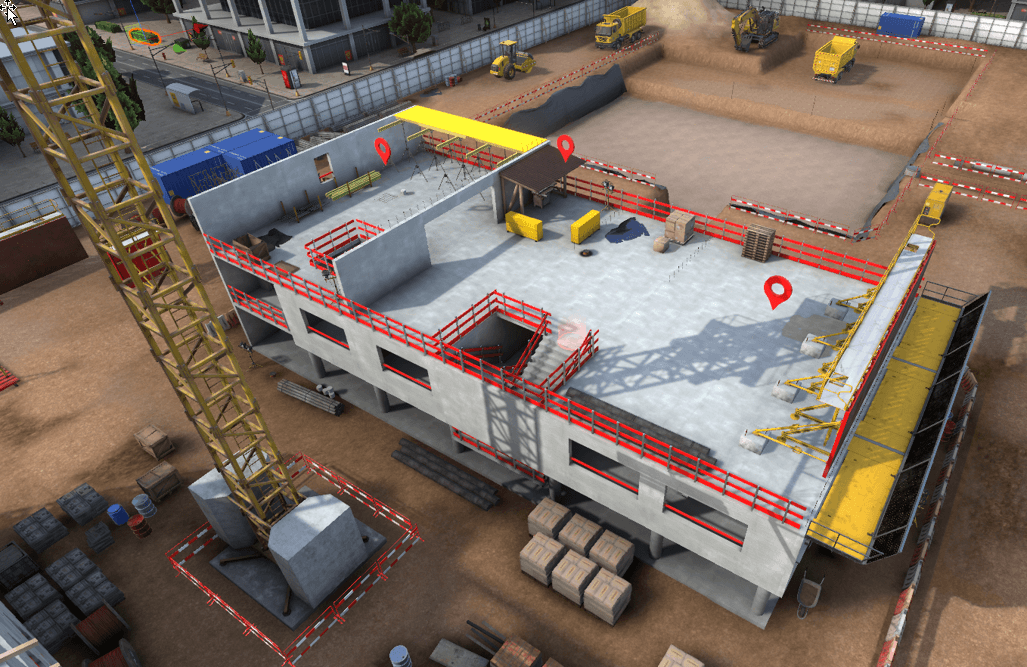
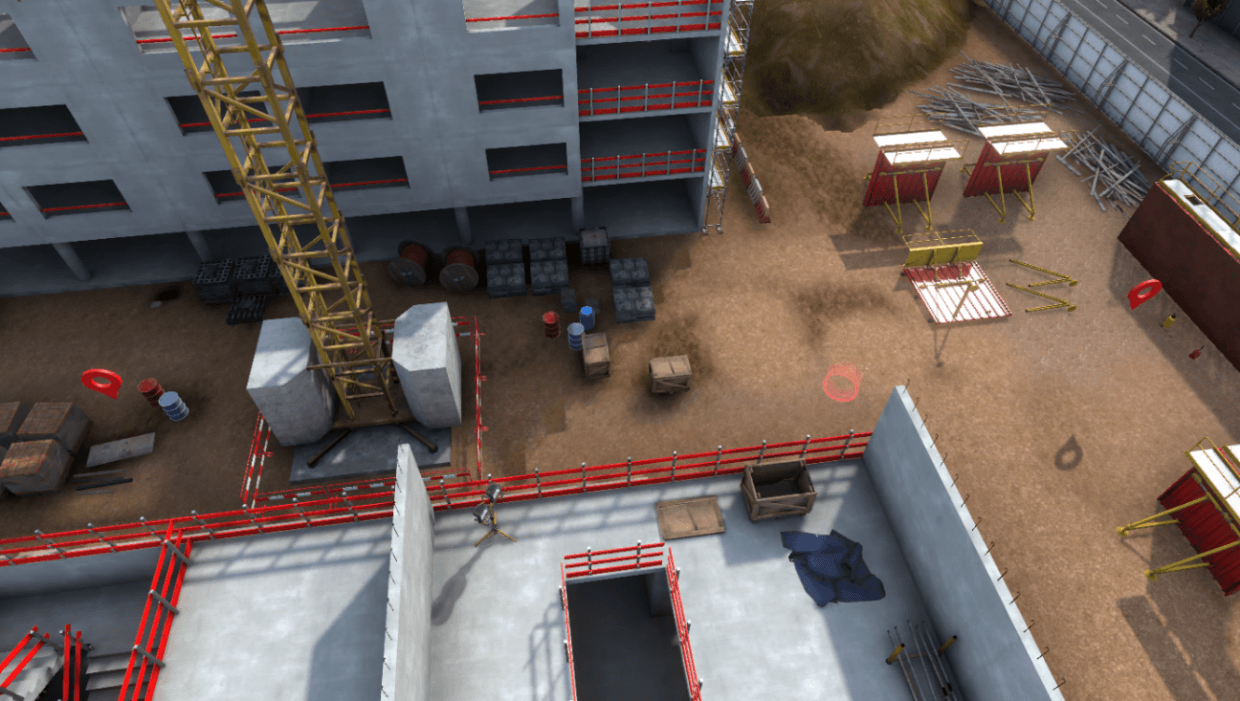
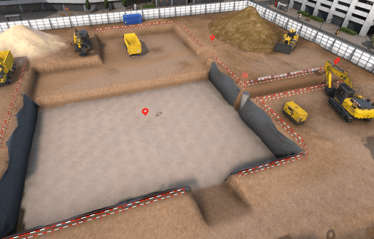
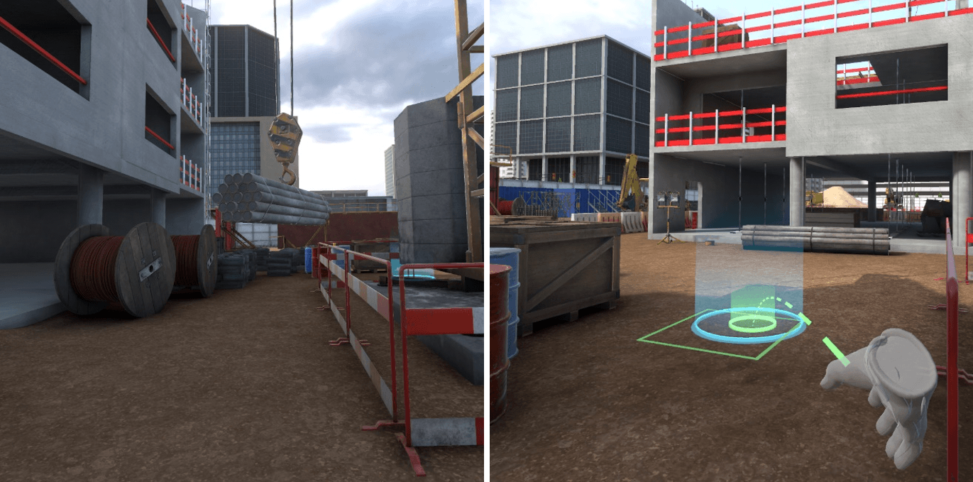
The guided mode takes place on one of the three construction site zones. The user must identify then secure the different dangers present in the zone selected.
Several work stations are present in a zone and are identified by a floating marker above the them.
The user is free to go on the workstations in the zone in the order that he wishes. He need only position himself under a marker to activate the sequence of phases specific to this workstation.
Once he is on a workstation, user movements are limited, he can’t directly deal with dangers in the zone.
Exercise evaluation criteria
![]() Identification : capacity to correctly identify and classify the
dangers.
Identification : capacity to correctly identify and classify the
dangers.
![]() Securing: capacity to correct dangers
Securing: capacity to correct dangers
![]() Completion time : capacity to finish the scenario in a defined time
Completion time : capacity to finish the scenario in a defined time
1.2.1. Identification procedure
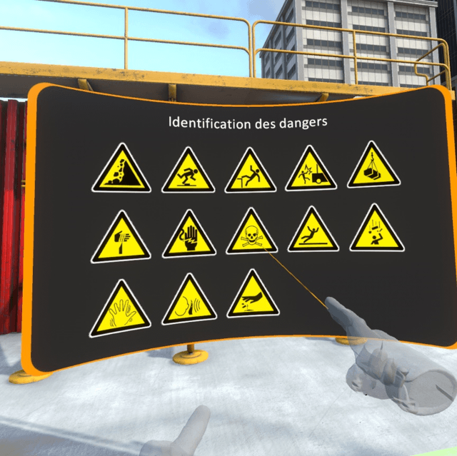
Once the user is on the workstation, he is asked to identify the different risks present.
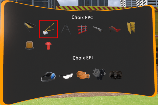
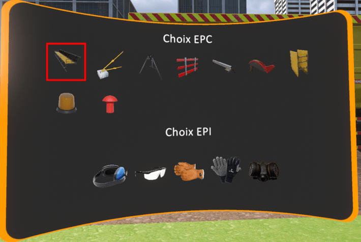
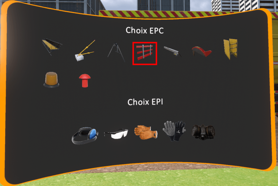
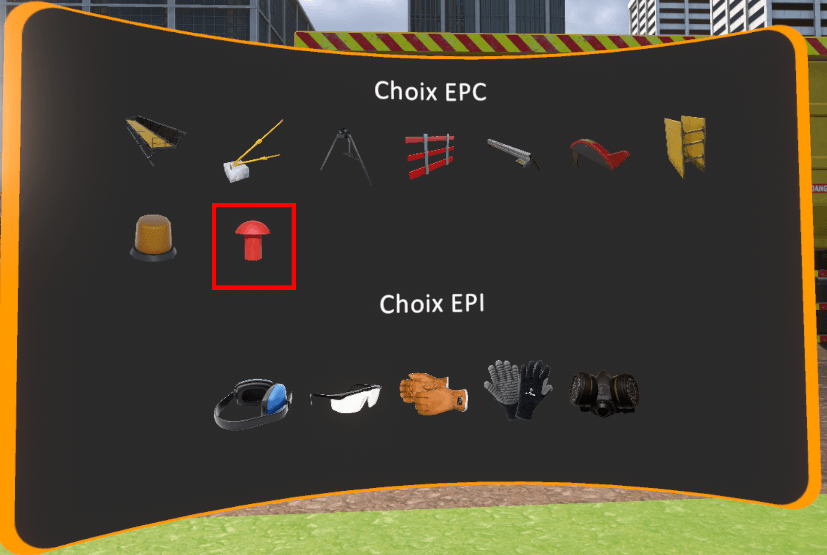
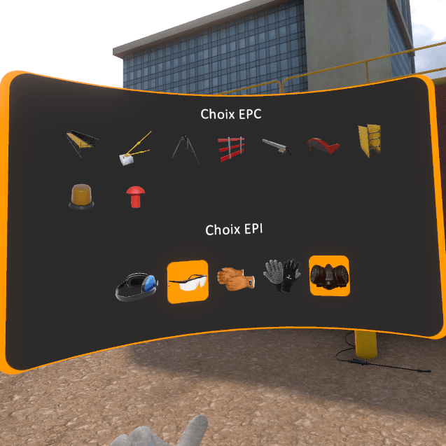
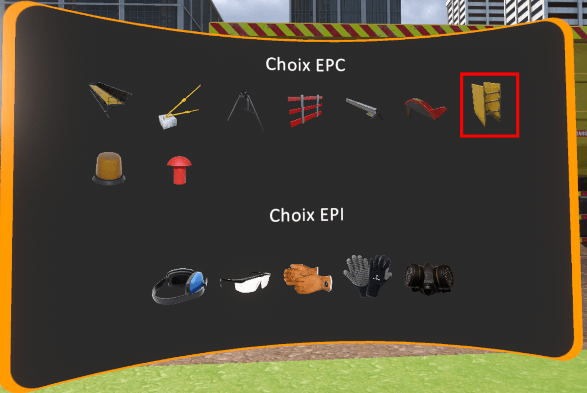
A screen appears in front of the user’s left hand with a list of risk pictograms. It is possible to select a pictogram using the right hand by pointing and clicking on the interaction key.
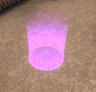
Once a pictogram is selected, the latter appears framed in orange. Now the user must point in the 3D scene at the exact location (or nearby) the risk that he wishes to identify and press again on the interaction key to place the pictogram on it.
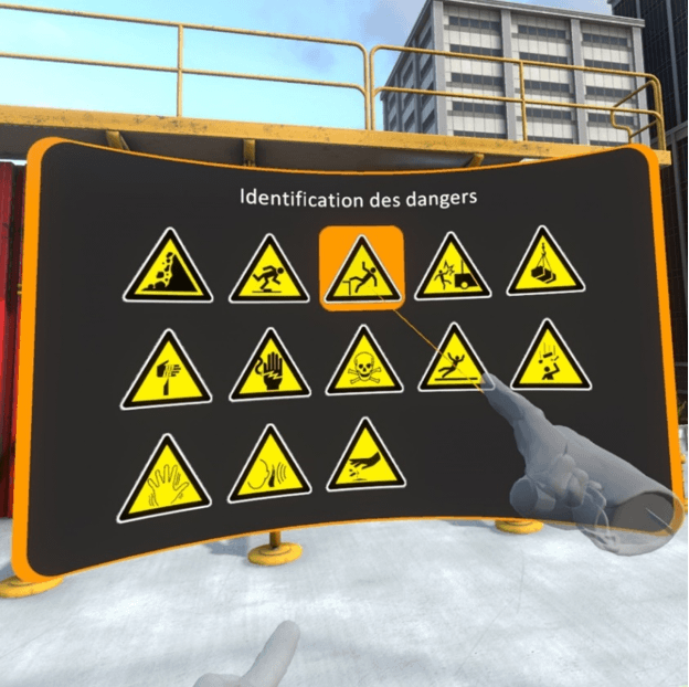
It is possible to delete a positioned pictogram by pointing at it and clicking on the cross.
Once all risks have been identified, the user must click on the buttom “Validate the identification” on the tablet at the level of the left wrist.
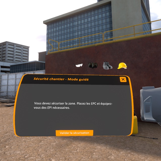
1.2.2. Securing procedure
Once dangers have been identified, the user is asked to secure the zone. The securing phases depend on the type of each risk, the security procedure for each workstation will be described later.
Once the workstation has been secured, clicking on the button « Validate securing » of the tablet enables the user to move on to the next step.
Once the identification of the security procedure has been completed on the first workstation, the user is asked to move on to the next workstation until he has completed all of the workstations in the zone.
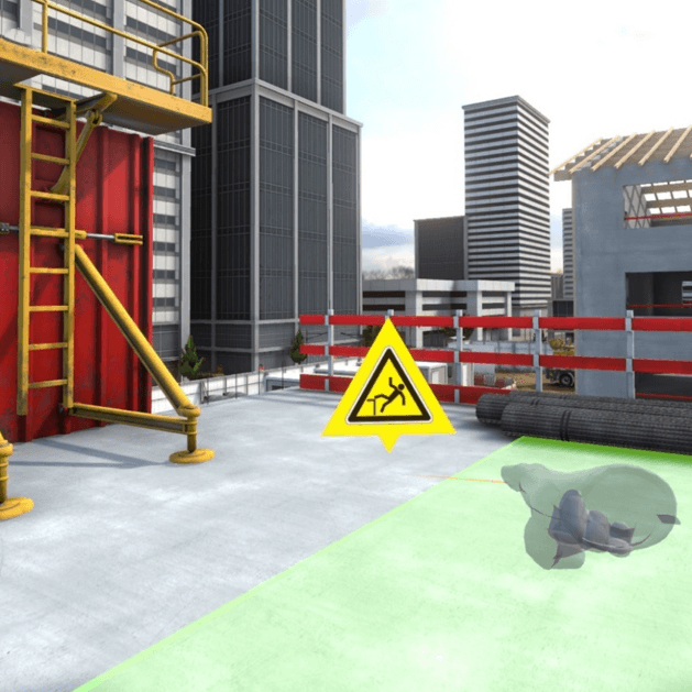
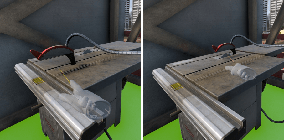
1.2.3. Zone assessment
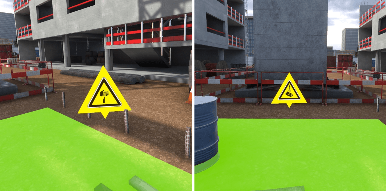
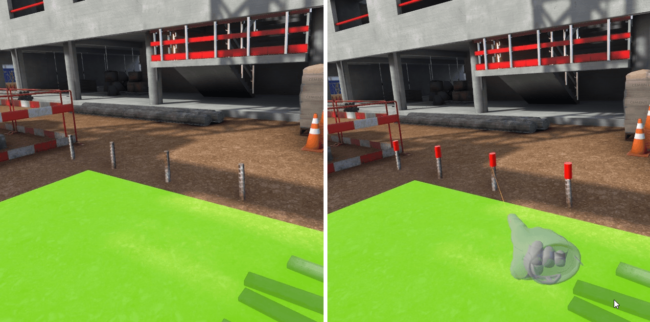
Once all the workstations have been completed, it is possible to move freely in the zone. Pop-ups on the different risks summarize if they have been correctly identified and secured.
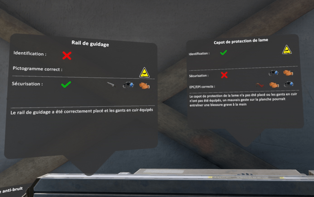
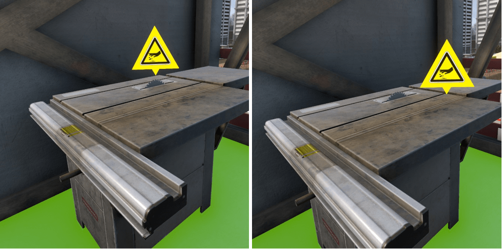
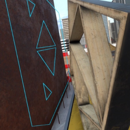
On the example above, the danger corresponding to the guide rail, has not been identified, no pictogram has been placed, so the correct pictogram is displayed. The security is correct, the blade guide has been placed, and the leather gloves and noise protection equipped.
For the danger of the blade protection cover, it was correctly identified by placing the pictogram but it has not been correctly secured. You can see that the gloves and noise protection gear have been equipped, but the cover has not been placed on the blade.
It is possible to terminate the exercise by clicking on the tablet cross, or by going on to the red marker on the ground.
1.2.4. R+2 Structural work area
Upon arrival on the zone, three workstations are available, it is possible to move freely to one of the three workstations to begin the risk identification.
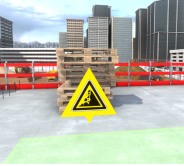
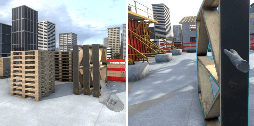
Workstation 1 – Coffrage de voile banché /Formwork for a
reinforced wall
There are three dangers on this workstation :
-
Unstable pile of pallets
-
Missing concrete ballast on the formwork
-
Missing platform
Identification
Ensuring security
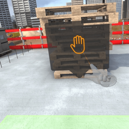
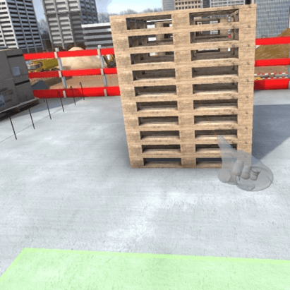
To secure the pile of unstable pallets, the user must get close enough to it for a pop-up to appear. A click on this pop-up will result in the pallets being positioned in a more stable position.
To secure the panels in danger of falling over, click on the « concrete ballast » PPE on the equipment selection window then point to the ground in front of the panels. Then click on the interaction key. This will result in placing the concrete weights against the panels to stabilize them.
To secure the void near the panels, the user must select the platform in the list of PPE available and point the controller in the direction of the void. Clicking on the interaction key will position the platform in the right place.
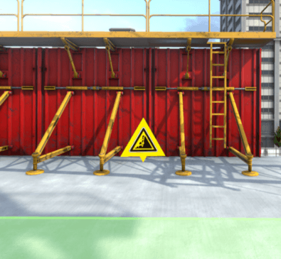
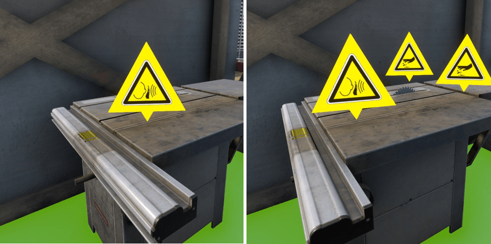
Workstation 2 – Cutting formwork panels
There are three dangers on this workstation :
-
Lack of blade guard
-
Missing guide
-
Saw noise
Identification
Securing procedure
To secure the blade, select the blade guard in the list of PPE available then point and click on the saw blade with the interaction key. This will position the blade guard on the blade. It will also be necessary to put on the leather gloves available in the list of PPE.
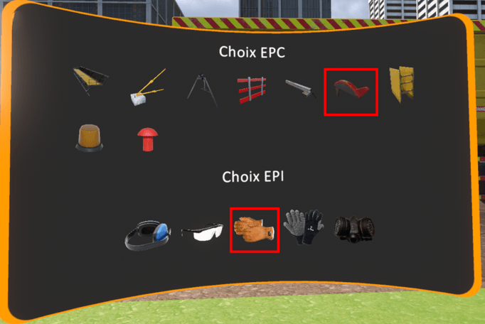
To secure the cutting, it is necessary to install the missing blade guard. It can be found in the list of PPE and positioned by clicking and pointing with the interaction key.
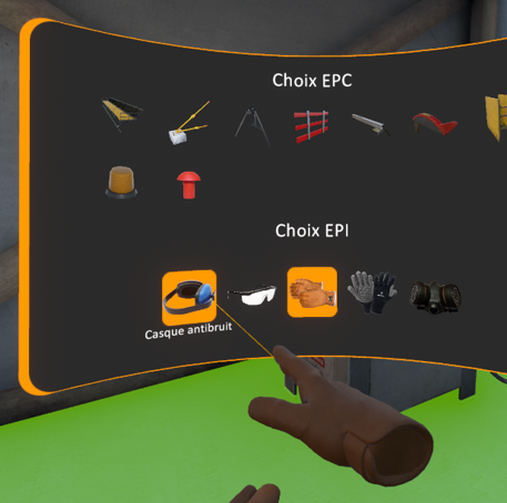
The third danger in the zone concerned is the noise of the saw.
To protect yourself from the noise, the noise protection gear must be equipped from the list of PPE in addition to the leather gloves.
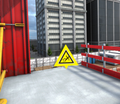
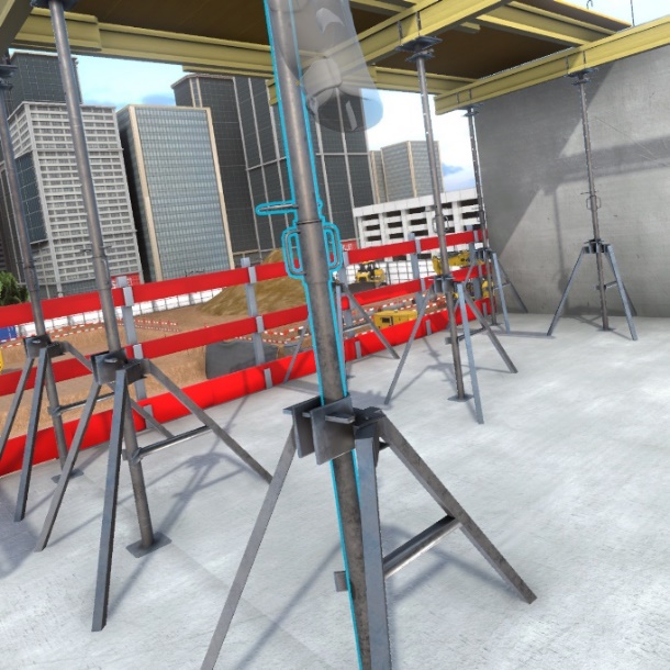
Workstation 3 – Formwork floor shoring
There are three dangers on this workstation :
-
Missing guardrail
-
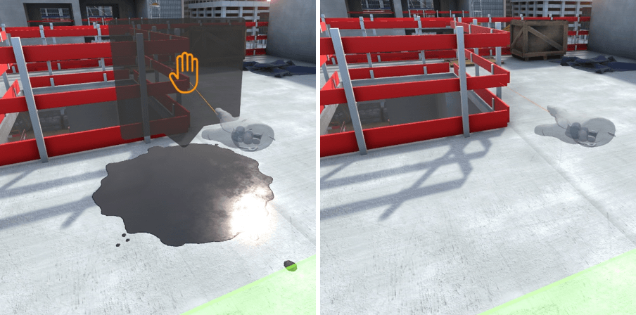
Oil stain
-
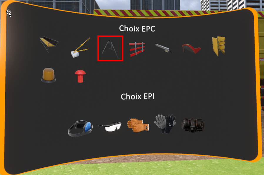
Lack of tripods on props.
Identification
Ensuring security
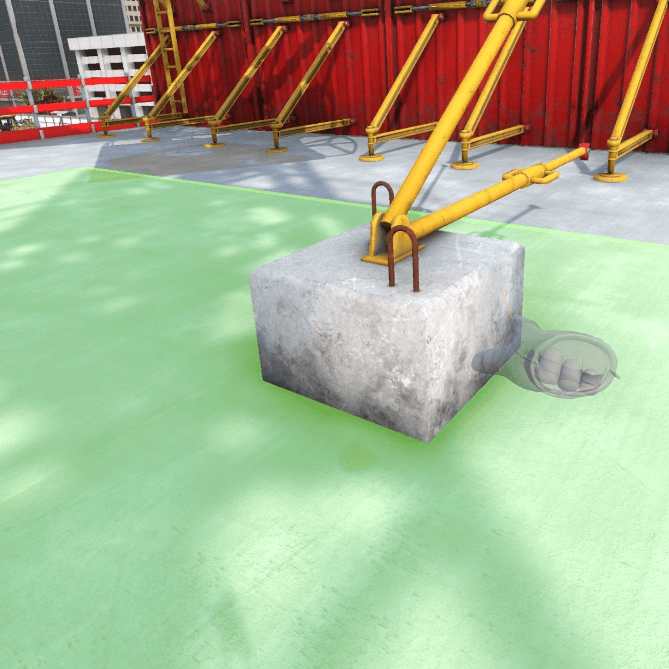
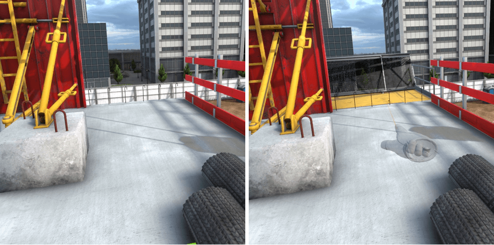
To secure the void at the elevator shaft, you must select the guard rail from the list of EPC, point at the void and click on the interaction key.
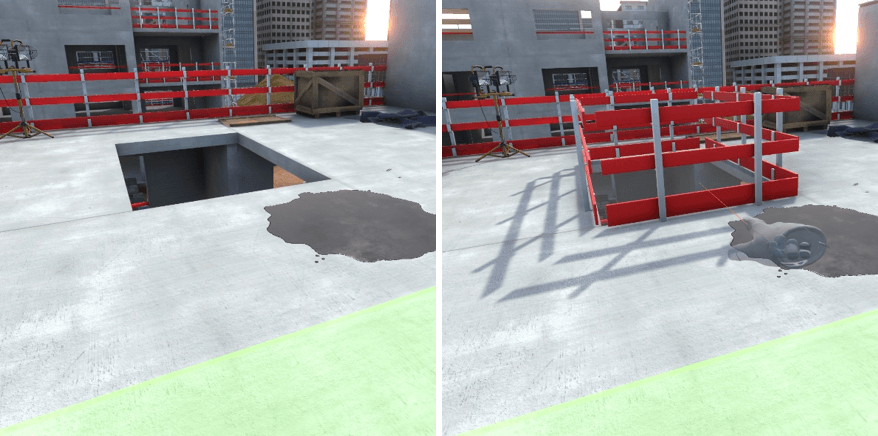
To eliminate the oil stain on the ground, you must get closer to it till a pop-up appears. Clicking on the pop-up will eliminate the oil stain.
To position the tripod on the props, they must be selected in the list of PPE then point in the direction of a prop and click on the interaction key. They will be positioned on the ground.
1.2.5. R0 Zone structural work preparation
Upon arrival at the zone, two work stations are available, it is possible to move around freely at one of the two work stations to begin the risk identification.
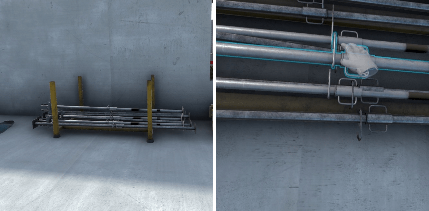
Workstation 1 – Lifting of scaffolding packages
There are two dangers on this workstation :
-
Unprotected holding steels
-
Crane.
Identification
Ensuring security
To secure the unprotected holding steels, you must select the steel protection end caps from the list of PPE and place them on the holding steels on the ground.
The danger due to the crane can’t be secured, it is necessary to make sure not to get close to the load carried by the crane when it manoeuvres.
Workstation 2 – Cleaning, preparation of the panels
The dangers on this workstation are related to the toxicity of the form release agent.
Identification
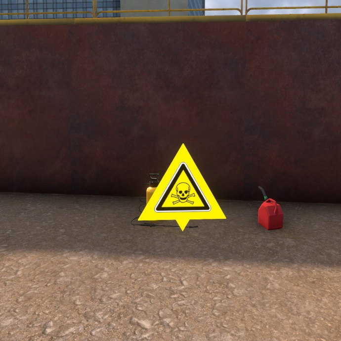
Ensuring security
To secure this workstation, it is necessary to equip two PPE available on the PPE selection screen. A gas mask to protect against toxic fumes from the form release agent as well as protective glasses to prevent any projections in the eyes.
1.2.6. R-1 Earthwork area
Upon arriving at the zone, three workstations are available. It is possible to move freely at one of the three workstations to begin the danger identification.
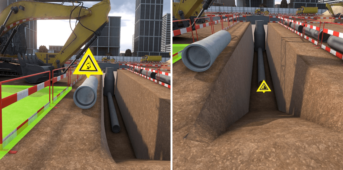
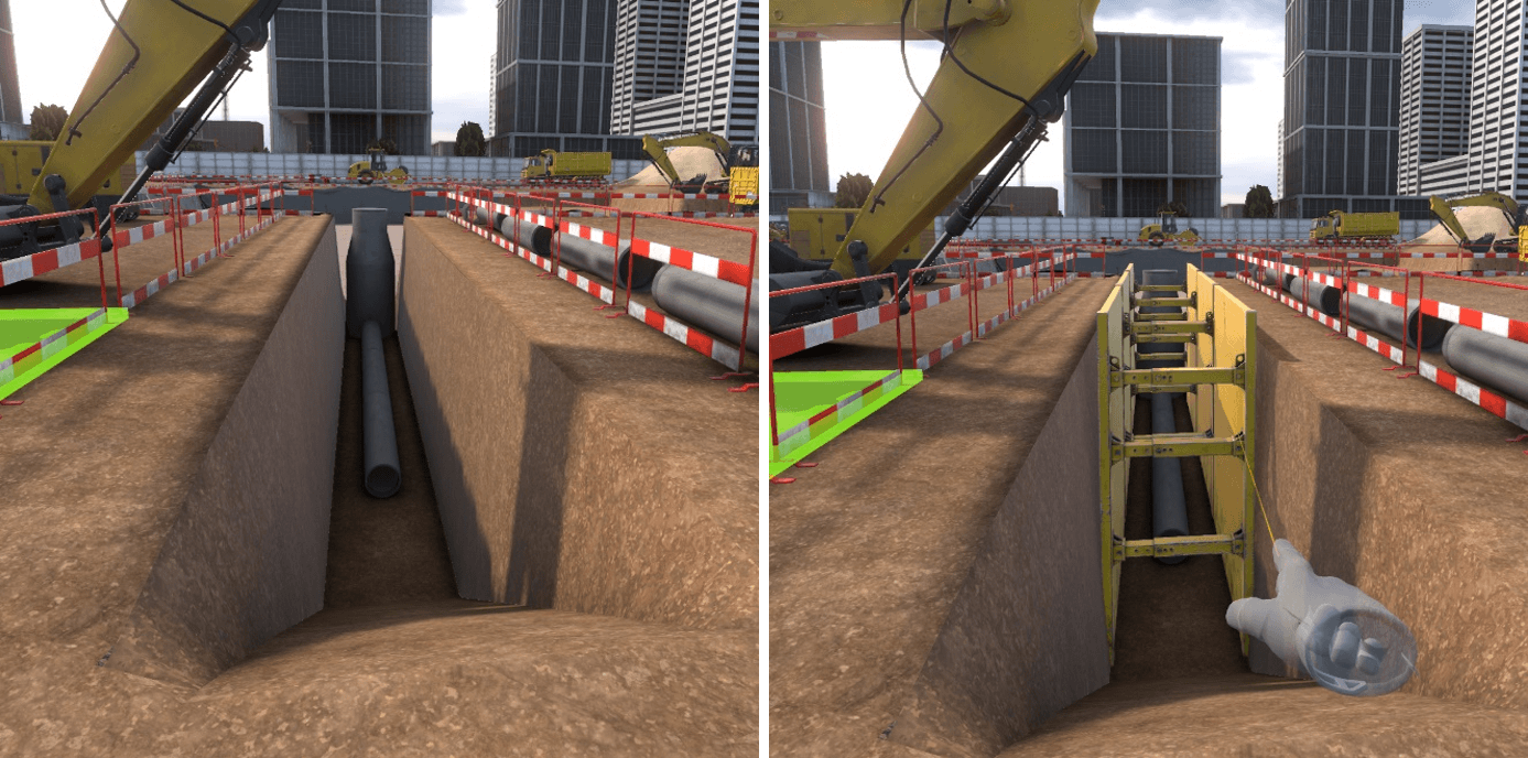
Workstation 1 – Laying a pipe at the bottom of the trench
There are two dangers at this workstation:
-
A pipe is at the edge of the trench and could fall into the trench. et pourrait basculer dans la tranchée.
-
The walls of the trench are not supported by shoring and could collapse.
Identification
Ensuring security
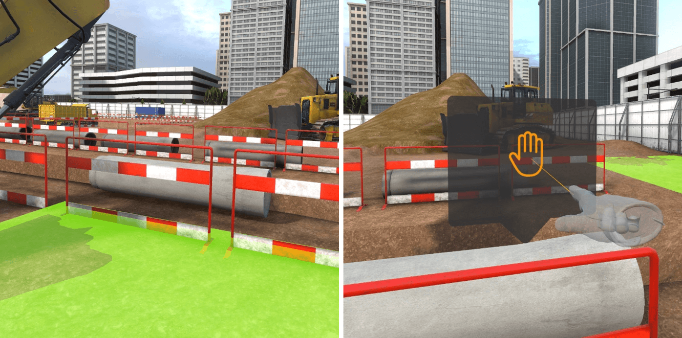
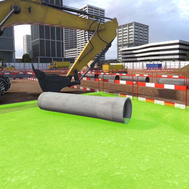
To secure the pipe, you need to get close enough for a pop-up to appear. Clicking on this pop-up will position the pipe in a less dangerous position.
To secure the trench, first select shoring in the list of PPE available, then place them by pointing and clicking on the trench walls.
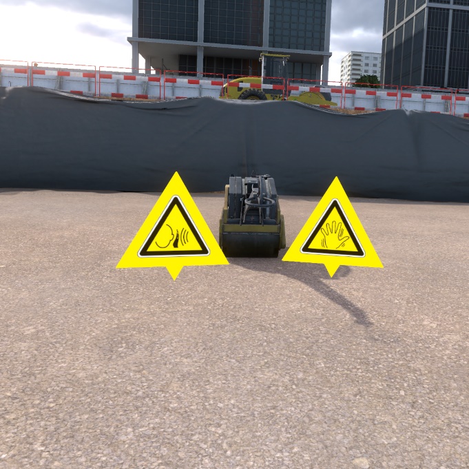
Workstation 2 – Soil compacting
The dangers on this workstation are the intense noise of the compactor, and the strong vibrations under usage.
Identification
Ensuring security
To secure this workstation, it is necessary to equip the anti-vibration gloves as well as hearing protection muffs, which are both available in the PPE list.
Workstation 3 – Topographic control of the platform
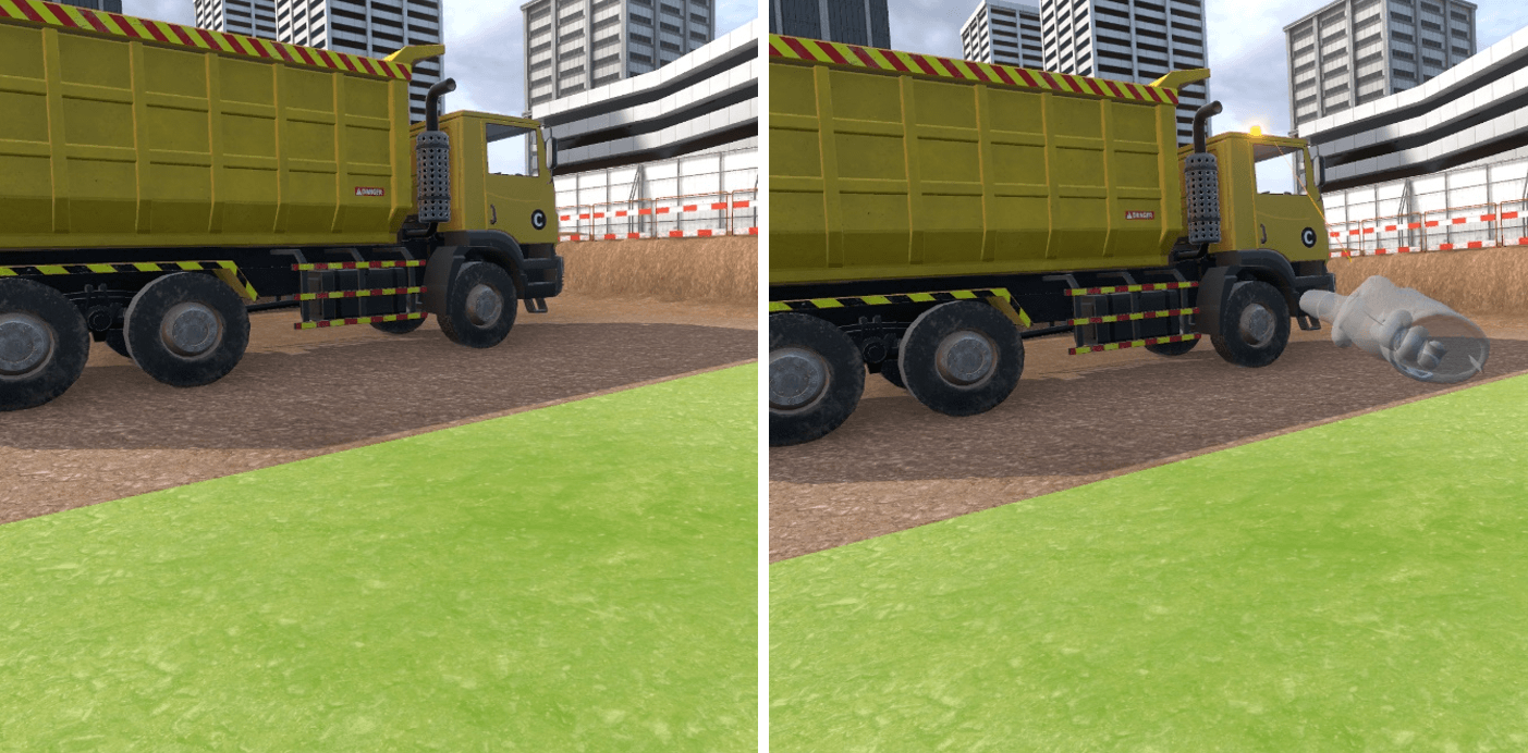
The danger on this workstation is the truck getting ready to back up.
Identification
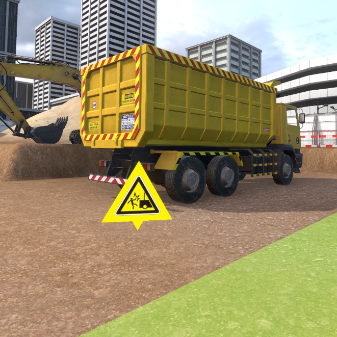
Ensuring security
For the security phase, select the flashing light from the list of PPE and place it on the truck by pointing at it and clicking on the interaction key.

1.3. Evaluation
In evaluation mode, the user is asked to perform an action on the construction site. He or she has the possibility of securing the dangers that he encounters. If he does not do it, and he puts himself in danger, a fatal error takes place which puts an end to the exercise. There is an evaluation exercise per workstation available on the construction site.
Exercise evaluation criteria
![]() Ensuring security : capacity to see and correct the dangers before
arriving at the workstation.
Ensuring security : capacity to see and correct the dangers before
arriving at the workstation.
![]() Execution time : capacity to finish the scenario in a defined time
Execution time : capacity to finish the scenario in a defined time
1.3.1. R+2 - Workstation 1 – Wall formwork
IInstruction :
Place a formwork dummy at the highlighted location behind the formwork panels.
To complete this objective, grasp one of the formwork dummies placed near the palettes and place it on the blue highlighted zone behind the formwork panels. To do this safely, it will be necessary to secure the different zone dangers including:
-
Stabilizing the pile of pallets by getting close to them and clicking on the popup
-
Placing the concrete weights against the formwork panels
1.3.2. R+2 - Workstation 2 – Formwork panel cutting
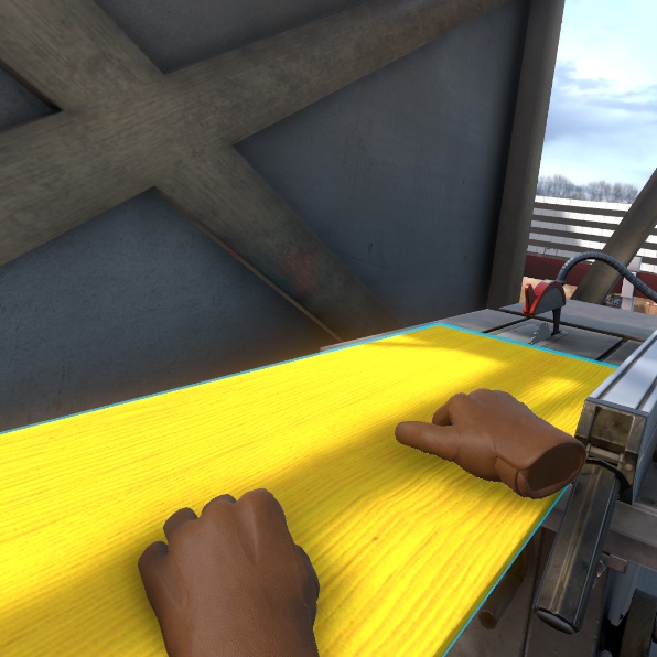
Instruction : Cut the formwork panel present on the cutting station.
To complete this objective, simply grasp the formwork panel placed on the saw and move it to perform the cut.
To do this safely, first you must :
-
Place the blade guard on the saw
-
Place the blade guide on the platform
-
Put on the leather gloves
-
Put on the noise protection gear.
1.3.3. R+2 - Workstation 3 – Floor shoring formwork
Instruction : take a prop from the basket and place it in the highlighted location.
To complete this objective, grasp a prop in the basket and place it at the location highlighted in blue being careful to first secure the zone so as not to set off a fatal error:
-
Clean up the oil spot by carefully getting close to it and clicking on the pop-up that appears over it.
-
Position guard rails around the elevator shaft vide
-
Place tripods around props.
1.3.4. R0 - Workstation 1 – Lifting scaffolding packages
Instruction : Go to the highlighted spot safely.
To complete this objective, go to the blue marker located around the crane, being careful to place the protective end caps on the steel holders on the ground. You must also wait for the passage of the crane carrying the load before passing to avoid being hit.
1.3.5. R0 - Workstation 2 – Cleaning, preparation of the panels
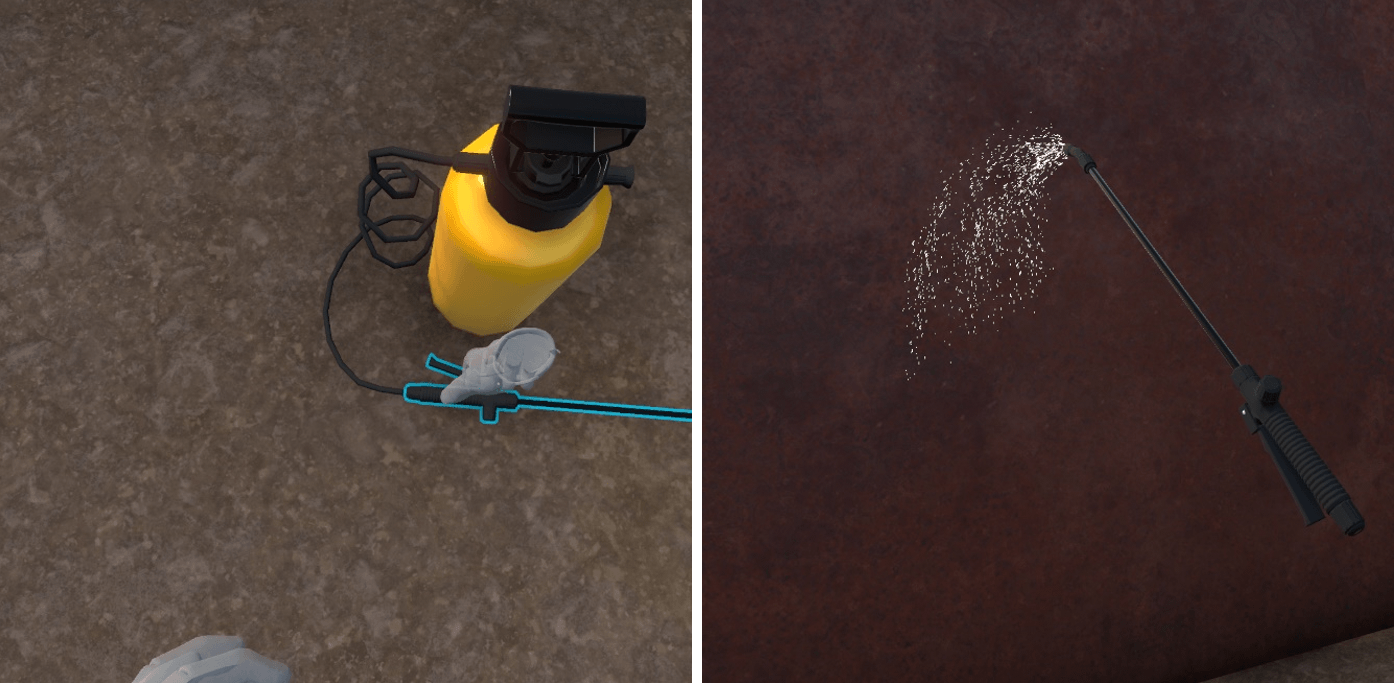
Instruction : Spray the form release agent on the formwork panels
To complete this objective, grasp the spray with the objective grasp button then press on the interaction key to spray the product. Before doing this, to be safe, you must :
-
Put on the gas mask
-
Put on the protective glasses.
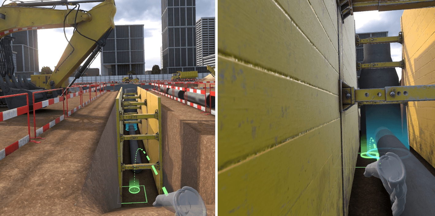
1.3.6. R-1 - Workstation 1 – Laying pipe in the bottom of the trench
Instruction : go down into the trench at the highlighted location to control the slope of the waste water pipes.
To complete this objective, you must enter the trench at one end on the blue marker and stay there a few instants:
First you must :
-
Move the pipe that risks falling into the trench by getting closer and clicking on the pop-up that appears over it.
-
Place shoring on the trench walls to prevent collapse.
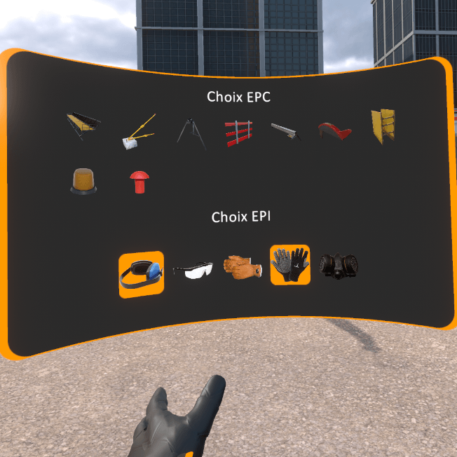
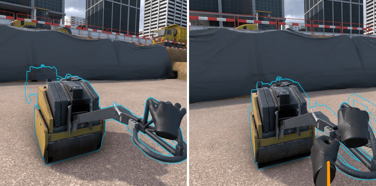
1.3.7. R-1 - Workstation 2 – Soil compacting
To complete this objective, grasp the compactor with the object grasp key and keep pressing the key till the compactor reaches the highlighted zone. First you must secure the situation:
-
Put on anti-vibration gloves available in the PPE list.
-
Put on the noise protection gear available in the PPE list.
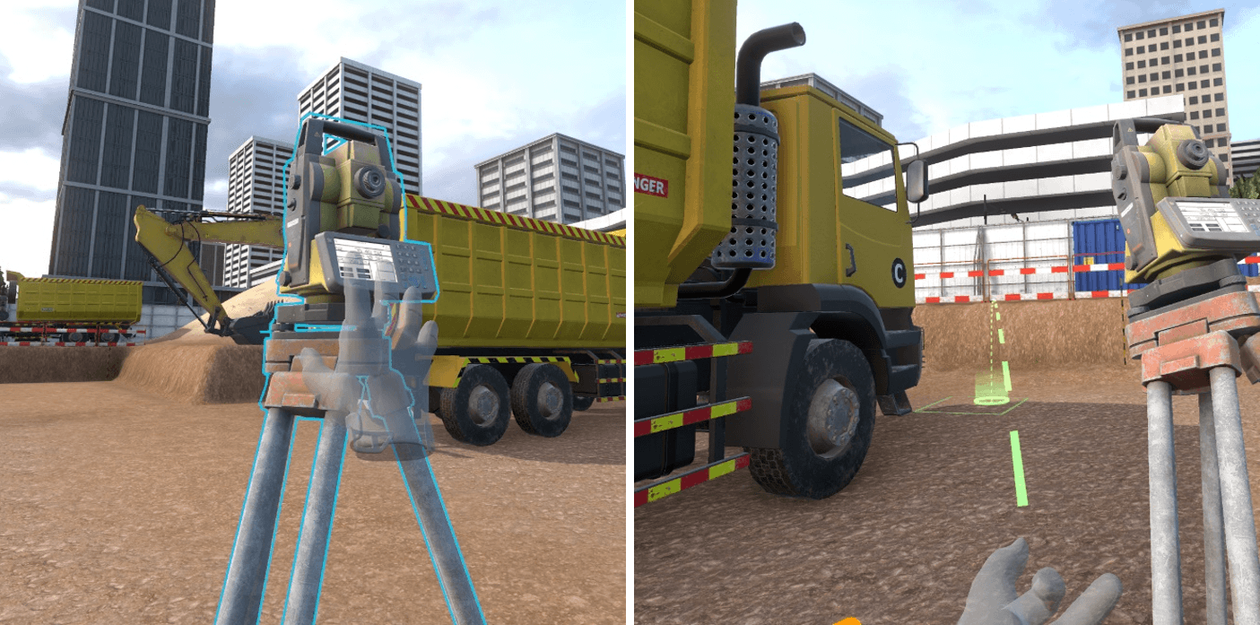
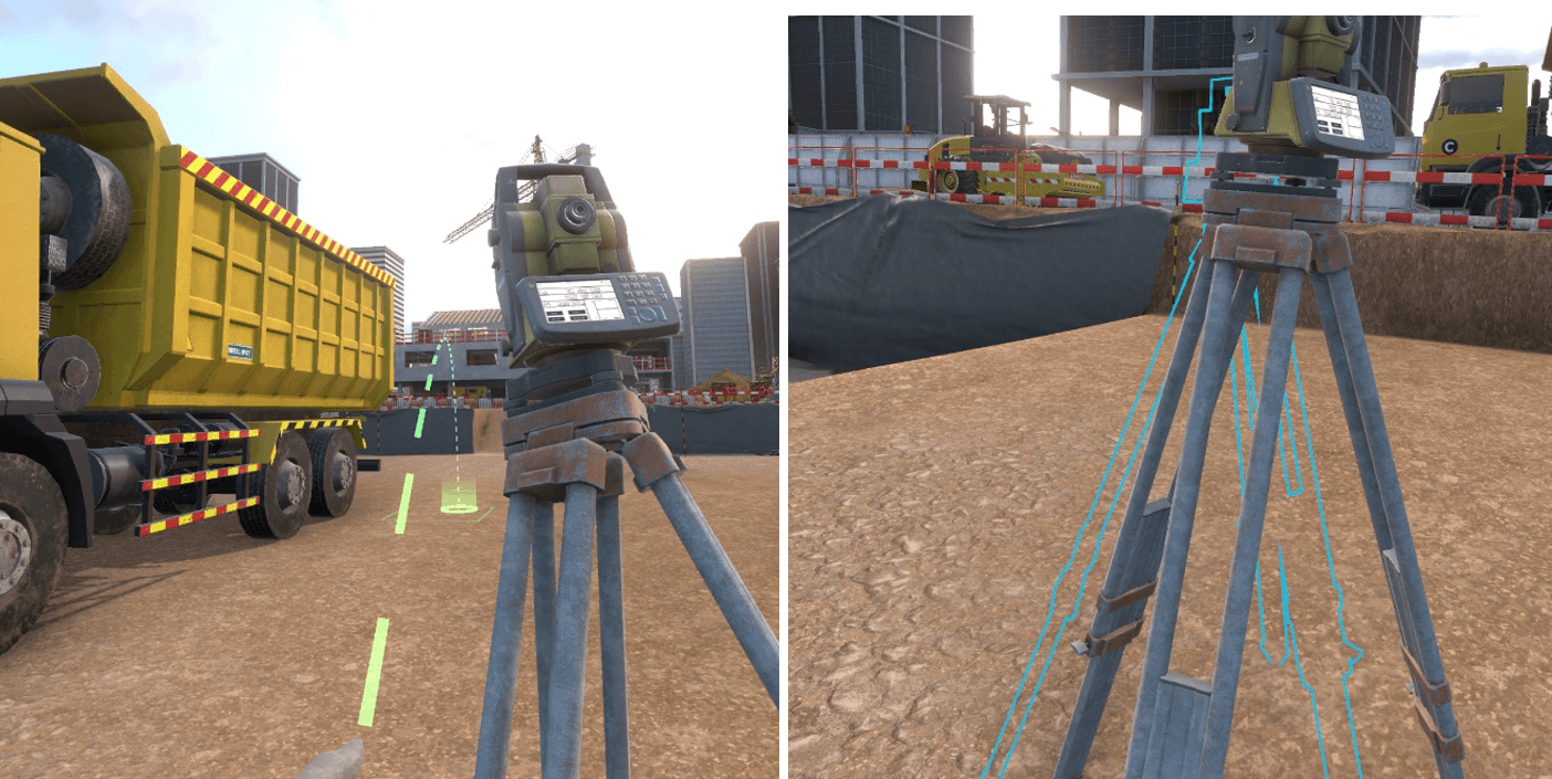
1.3.8. R-1 - Workstation 3 – Topographical control of the platform
Instruction : Move the tacheometer to the highlighted location to make a measurement
To complete this objective, take the tacheometer by pressing on the object grasp button and holding it down. Then walk around the front of the truck and place the tacheometer on the blue highlighted zone. First place the missing flashing light on the truck by selecting it in the PPE list and clicking on the truck with the interaction key.
1.4. Setting up the exercises
The default exercise settings can’t be changed but it is possible to create editable copies whose settings can be changed by the trainer to vary the grading according to several criteria.
1.4.1. Parameters
Name of the exercise : enables to change the name of the exercise as it is displayed in the simulator
Level : corresponds to the level of the exercise, when copying an exercise by default it is important to not modify this parameter (beginner = free mode, advanced = guided mode, expert=evaluation mode)
Validation threshold : corresponds to the value of the final score (percentage) below which the exercise is considered a fail.
Consideration threshold : score below which the result of the exercise will not be taken into account.
1.4.2. Sensors
| Min | Target | Max | |
|---|---|---|---|
FREE MODE |
|||
Distance travelled |
Distance in meters to travel below which the score will be 0 % |
Distance in meters to travel starting at which the score will be 100 % |
|
Time before an accident |
Duration in seconds spent on the exercise below which the score will be 0 % |
Duration in seconds spent on the exercise starting from which the score will be 100 % |
|
ACCEPTANCE and USE |
|||
Identification |
Number of dangers identified to obtain a score of 100 % |
Indicative value of the number of dangers present on the zone for this exercise (should not be modified) |
|
Securing |
Number of dangers secured to obtain a score of 100 % |
Indicative value of the number of dangers present on the zone for this exercise (should not be modified) |
|
Duration of execution |
Duration in seconds spent on the exercise below which the score will be 100 % |
Duration in seconds spent on the exercice above which the score will be 0 % |
1.4.3. Simulation variable
Percentage of malus per identification error: percentage of malus applied to the identification score for a danger in this exercise, for each incorrect picture placed in addition to a correct picture (for example, for a value of 10 at this variable, if a correct picture is placed as well as an incorrect picture near the same risk, a malus of 10% will be applied to the identification score for this risk).
Percentage of malus per securing error : percentage of malus applied to the securing score for a risk of this exercise, for each attempt to place an incorrect PPE at the expected securing location.
Percentage of malus per extra PPE equipment : percentage of malus applied to the securing score for a danger of this exercise, for each additional un-necessary PPE equipped. (example: the value of the variable is 10, a risk requires wearing noise protection muffs but protective glasses are also equipped, so the malus would be 10% on the securing score for this risk).